Color image processing device and color image processing method

Inactive Publication Date: 2008-01-22
MURATA MASCH LTD
View PDF8 Cites 0 Cited by
  • Summary
  • Abstract
  • Description
  • Claims
  • Application Information

AI Technical Summary

Benefits of technology

[0006]An advantage of the present invention is to provide a color image processing device which can enlarge or reduce an image under an arbitrary rate of magnification at a low cost, without enlarging the size of the circuitry.
[0007]According to a first aspect of the present invention, a color image processing device includes n line sensors (line image sensors) arranged with a prescribed interval L between one another, an image data output unit which outputs image data from the line sensors under a prescribed cycle, and a line memory which stores image data for a plurality of lines and outputs the image data with a delay.
[0008]According to a second aspect of the present invention, when P is an interval between pixels in a sub scanning direction during a scanning operation using 100% magnification, the number of pixels which increases and decreases by the rate of magnification is calculated by N·L / P. Then, it is determined which cycle is to be selected in accordance with a decimal part d of the calculated number, and a number of delayed lines is determined in accordance with an integral part D. A determination for selecting a cycle and the number of delayed lines can be made by a simple calculation.
[0009]According to a third aspect of the present invention, the color image processing device further includes a table of the decimal part d and the selected cycle. Therefore, a determination for selecting a cycle can be made easily in accordance with the calculation and by referring to the table.

Problems solved by technology

However, according to the rate of magnification, there are cases when the color scanner cannot support image data just by the delay amount of the line.
However, there is a problem that the circuitry for an image processing device becomes extremely complicated.

Method used


Image

  • Color image processing device and color image processing method
  • Color image processing device and color image processing method
  • Color image processing device and color image processing method

Examples


Embodiment Construction

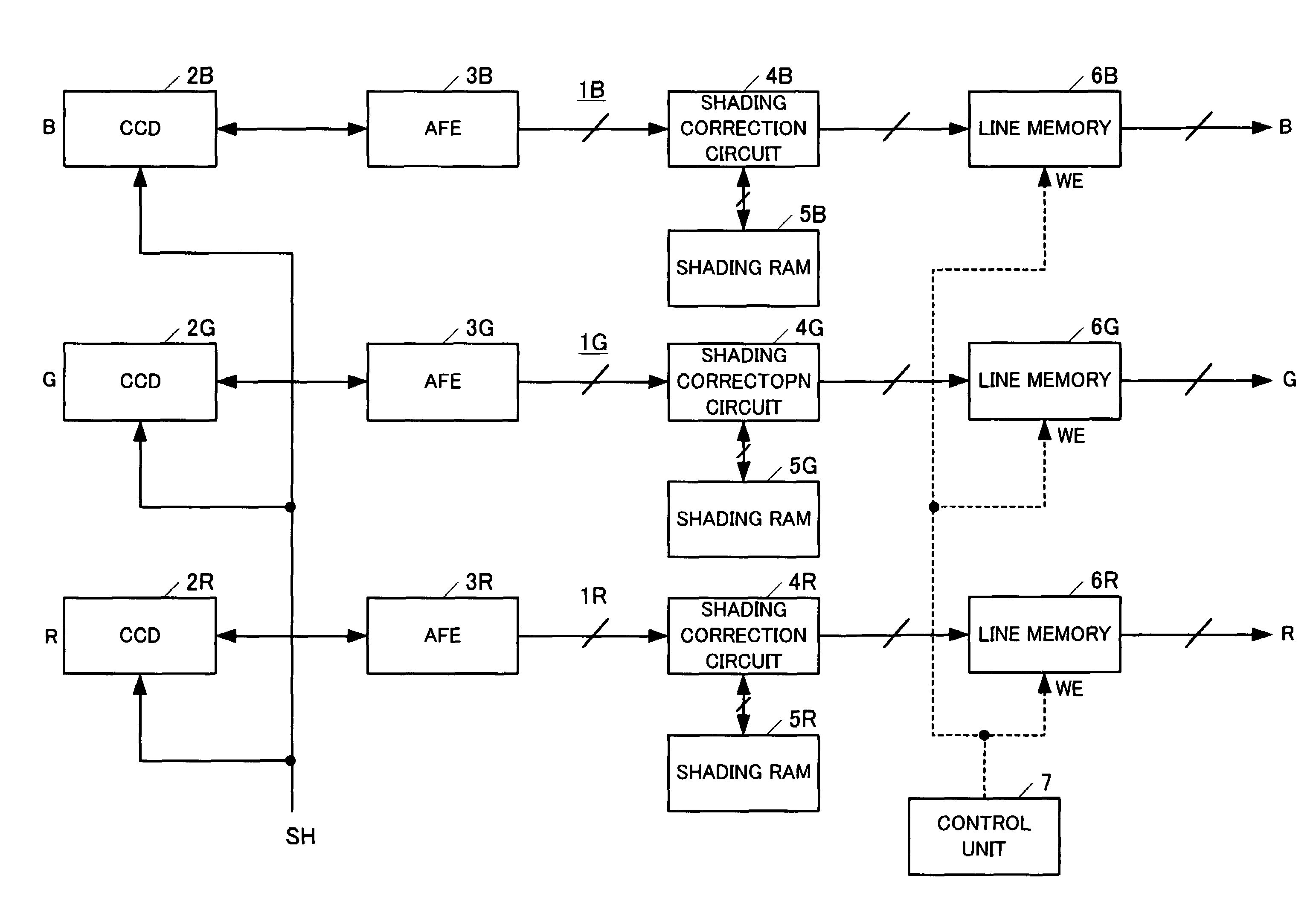
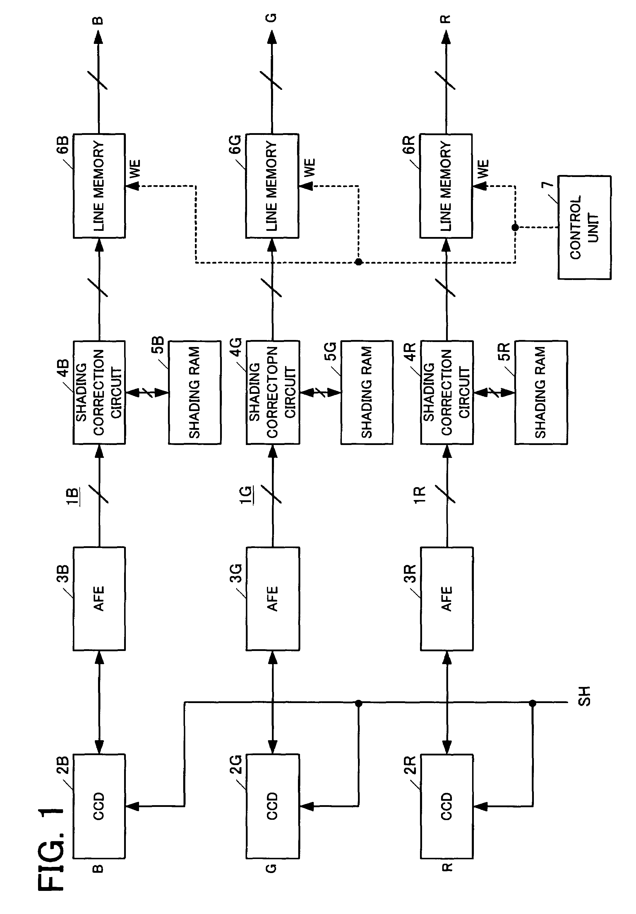
[0020]Embodiments of the present invention will be described in detail with reference to the accompanying drawings. FIG. 1 is a block diagram showing relevant parts of a color image scanning device which is an embodiment of the present invention. The color image scanning device includes a B signal processing unit 1B, a G signal processing unit 1G, an R signal processing unit 1R, and a control unit 7.

[0021]The B signal processing unit 1B includes a line image sensor 2B, an Analog Front End (AFE) circuit 3B, a shading correction circuit 4B, a shading Random Access Memory (RAM) 5B, and a line memory 6B. The G signal processing unit 1G includes a line image sensor 2G, an AFE circuit 3G, a shading correction circuit 4G, a shading RAM 5G, and a line memory 6G. The R signal processing unit 1R also includes a circuit like the B signal processing unit 1B and the G signal processing unit 1G. That is, the R signal processing unit 1R includes an AFE circuit 3R, a shading correction circuit 4R, ...


PUM


Abstract

A color image processing device includes n line sensors which are arranged with a prescribed interval L between one another, an image signal output unit which outputs image signals under a prescribed cycle from the line sensors and a line memory which stores the image signals for a plurality of lines and outputs the image signals with a delay. A control unit is provided for controlling to input one of the image signals of a certain cycle into the line memory, and to output an image signal from the line memory by delaying a certain number of lines, in accordance with a prescribed rate of magnification N.

Description

BACKGROUND OF THE INVENTION[0001]1. Field of the Invention[0002]The present invention relates to a color image processing device such as a color scanner, and a color image processing method used in the color image processing device.[0003]2. Description of the Related Art[0004]Color scanners are provided with line image sensors which are respectively formed from a charge coupled device (CCD) for each of the colors, red (R), green (G), and blue (B), wherein the line image sensors are provided in parallel to one another and displaced slightly from one another in a sub scanning direction. In this type of color scanner, since the line image sensors for each of the colors are provided in parallel to one another, the line image sensors cannot physically scan each of the colors on the same line of an original document at the same time. Therefore, a conventional color scanner includes a line memory which delays image data, and by maintaining a delay amount according to a rate of magnificatio...

Claims


Application Information

Patent Timeline
IPC IPC(8): G06F15/00G06T3/40G06T1/00H04N1/393H04N1/48
CPCH04N1/3935H04N1/486
Inventor NAMIKAWA, HIROFUMIMIMAMINO, KATSUSHI
Owner MURATA MASCH LTD
Why Eureka
Try Eureka