
Variable rate ignition

a variable rate ignition and gas turbine engine technology, applied in engine control, engine ignition, jet propulsion plants, etc., can solve the problems of increasing simplifying and increasing the cost of each wire, so as to simplify the design of the exciter and simplify the installation of the engine. , the effect of reducing the weight of each wir

Active Publication Date: 2008-01-29
PRATT & WHITNEY CANADA CORP
View PDF4 Cites 11 Cited by
  • Summary
  • Abstract
  • Description
  • Claims
  • Application Information

AI Technical Summary

Benefits of technology

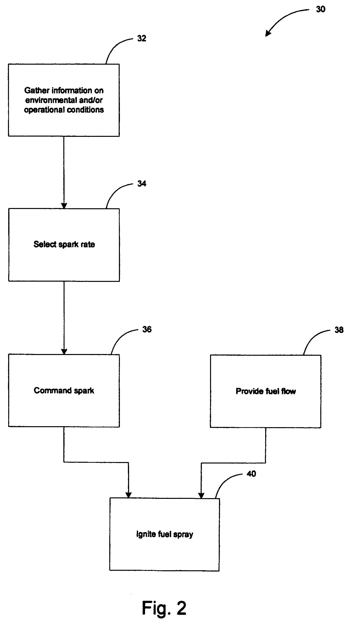
The present invention provides an improved method and apparatus for igniting a gas turbine engine using a variable rate ignition method. The decision process for determining the spark rate of the igniter is entirely ensured by the engine controller, simplifying the design of the exciter and reducing installation costs. The method takes advantage of knowledge and analysis of environmental conditions and / or operational conditions to optimize engine performance and prolong the life of the igniters. The system includes an engine controller, exciter, and igniter to command a spark and ignite the flow of fuel.

Problems solved by technology

This results in a simplification of the design of the exciter.
Each wire adds considerable weight and cost.

Method used


Image

  • Variable rate ignition
  • Variable rate ignition
  • Variable rate ignition

Examples


Embodiment Construction

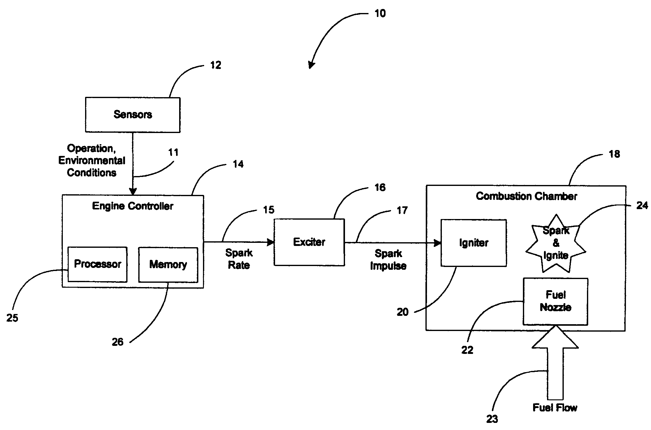
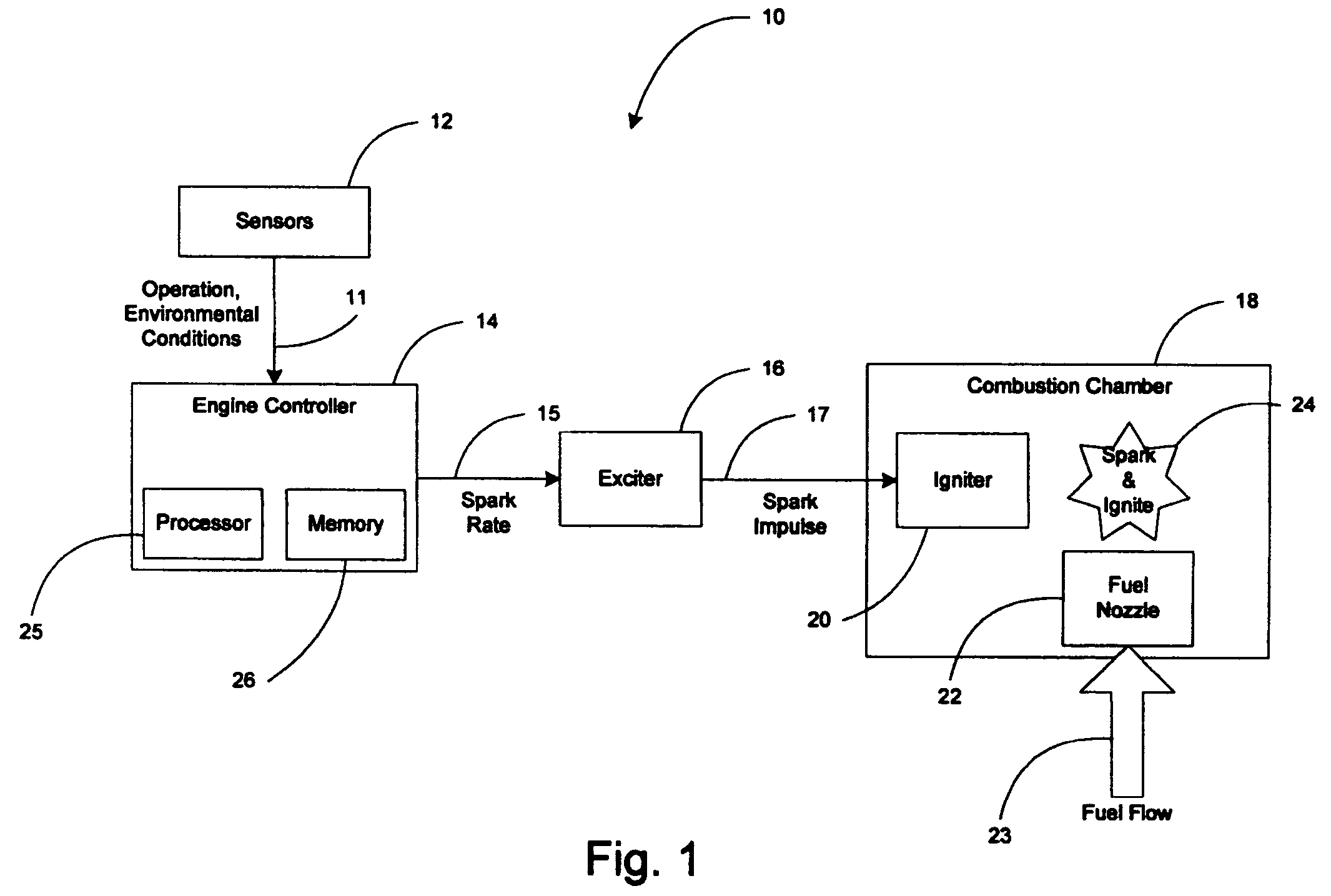
[0014]Referring to FIG. 1, there is shown a variable rate ignition system 10 according to an embodiment of the invention. System 10 includes Sensors 12, Engine Controller 14, Exciter 16, Igniter 20 and Fuel Nozzle 22. Igniter 20 and Fuel Nozzle 22 are included in Combustion Chamber 18 of a Gas Turbine Engine (GTE) (not shown).

[0015]It is foreseen that the present system 10 may be incorporated in any type of GTE installed, for example, aboard aircraft. System 10 may also be installed in any type of Auxiliary Power Units (APU). In aircraft GTEs, Engine Controller 14 is more commonly known as an Electronic Engine Controller (EEC) while in APUs it is referred to as an Engine Controller Box (ECB).

[0016]Sensors 12 are off-the-shelf items which are normally found in GTEs or APUS and are capable of sensing Environmental and / or Operational Conditions 11. Examples of such Environmental and / or Operational Conditions 11 include temperature of inlet air, engine oil, fuel, the exciter and exhaust...


PUM


Abstract

Variable rate ignition method and system that take advantage of knowledge and analysis of environmental conditions and / or operational conditions. A variable ignition rate for igniting the engine permits an optimal use of the igniters and thereby prolongs their life as well as its associated maintenance schedule. Operating costs and durability are also enhanced. Furthermore, flexibility is enhanced since any changes to the method of determining the best spark rate can be made through update in the software of the engine controller instead of change in the hardware (e.g., the exciter).

Description

TECHNICAL FIELD [0001]The present invention relates generally to ignition systems and method for gas turbine engines.BACKGROUND OF THE ART[0002]Prior art ignition exciters normally have fixed spark rates. These fixed spark rates are designed for an extreme point in the operating envelope of an engine. In order to accommodate this extreme requirement, the exciter has to be set to fire at the fastest rate at all times. This situation has the disadvantage of unduly inducing wear on spark igniters as well as reducing their lives. This results in having to replace igniters earlier than necessary and thereby increases already expensive engine maintenance costs. The stresses associated to the greater number of generated sparks / impulses also results in low durability and high operating costs for conventional exciters.[0003]Furthermore, systems exist where two or more fixed spark rates are manually selected according to the stage of operation. These systems provide limited flexibility.SUMMAR...

Claims


Application Information

Patent Timeline
Patent Type & Authority Patents(United States)
IPC IPC(8): F02C7/264
CPCF02C7/264F02C7/266F02P15/003F05D2270/301F05D2270/303F02P9/002
Inventor KUDRNA, RICHARD ROBERTMETHOT, DANIELLE
Owner PRATT & WHITNEY CANADA CORP
Learn More