Disc brake and monitoring device for such a disc brake

a disc brake and monitoring device technology, applied in the direction of drum brakes, brake types, mechanical devices, etc., can solve the problems of requiring a large number of components and radial mounting space, and achieve the effect of less mounting space and simple configuration

Active Publication Date: 2008-01-29
WABCO EURO BVBA SPRL
View PDF27 Cites 29 Cited by
  • Summary
  • Abstract
  • Description
  • Claims
  • Application Information

AI Technical Summary

Benefits of technology

[0008]It is an object of the present invention to improve the disc brake of the aforementioned kind such that it is of a simpler configuration, requires less mounting space, and detects the state of the brake precisely.

Problems solved by technology

This solution requires a large number of components.
This solution also requires mechanical machining of the bearing and contact surfaces and, again, radial mounting space is required.

Method used


Image

  • Disc brake and monitoring device for such a disc brake
  • Disc brake and monitoring device for such a disc brake
  • Disc brake and monitoring device for such a disc brake

Examples


Embodiment Construction

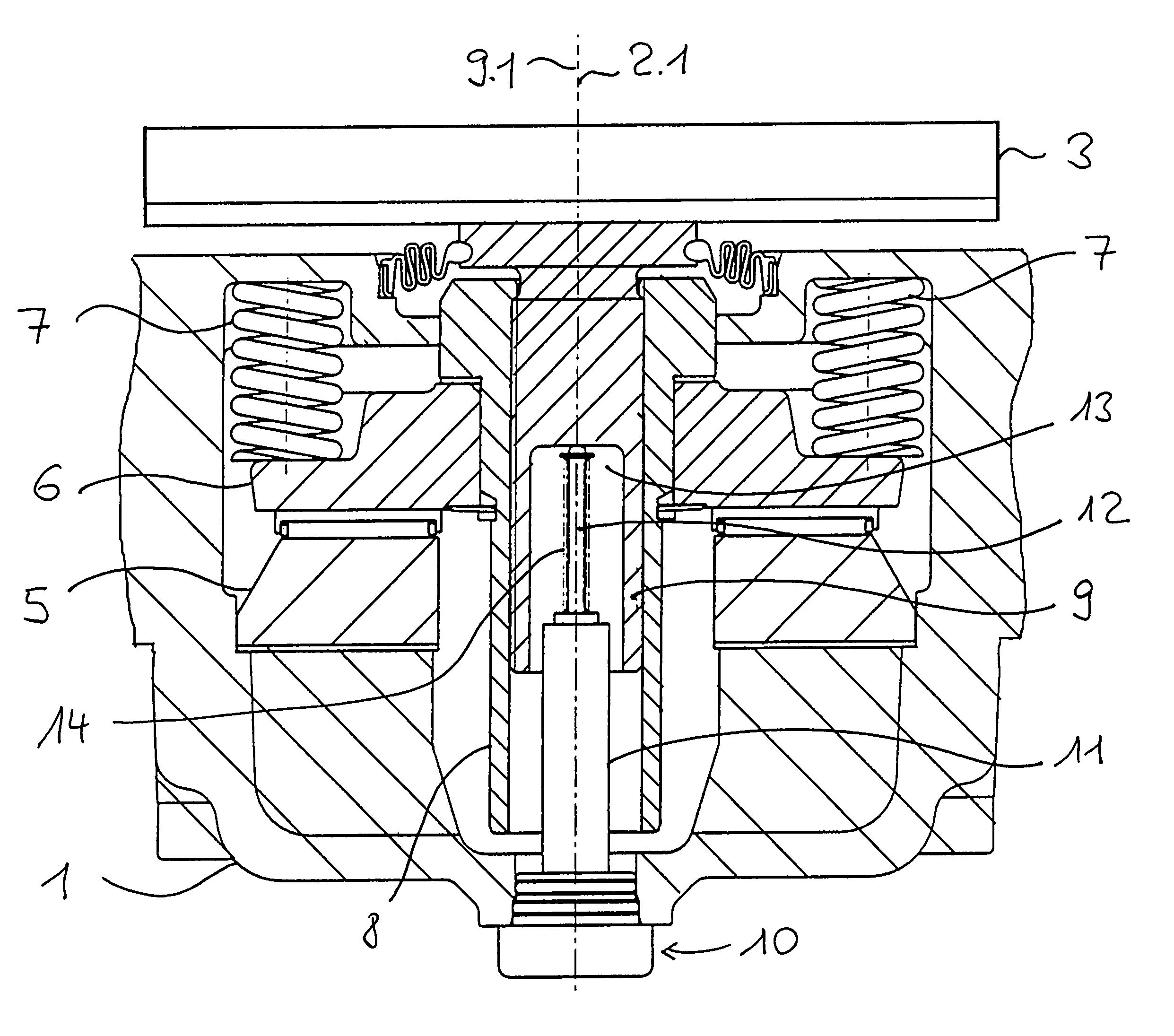
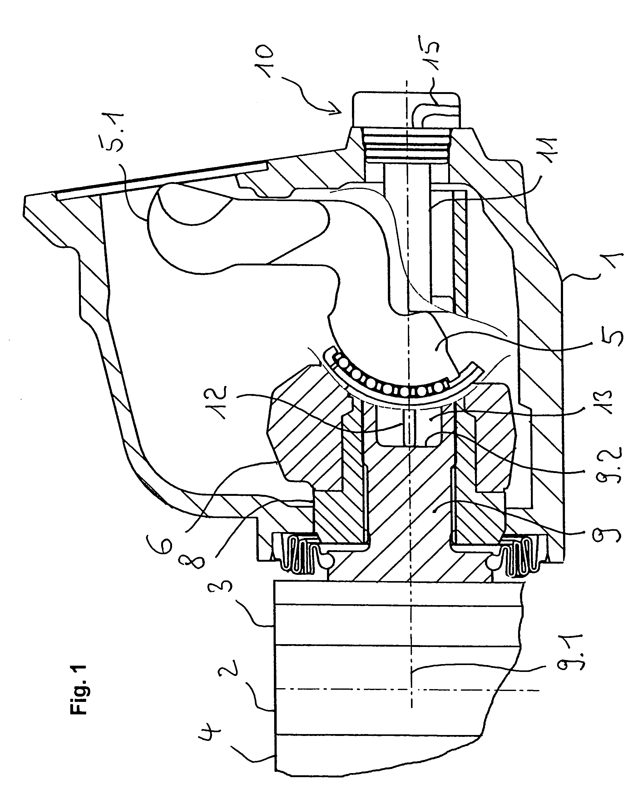
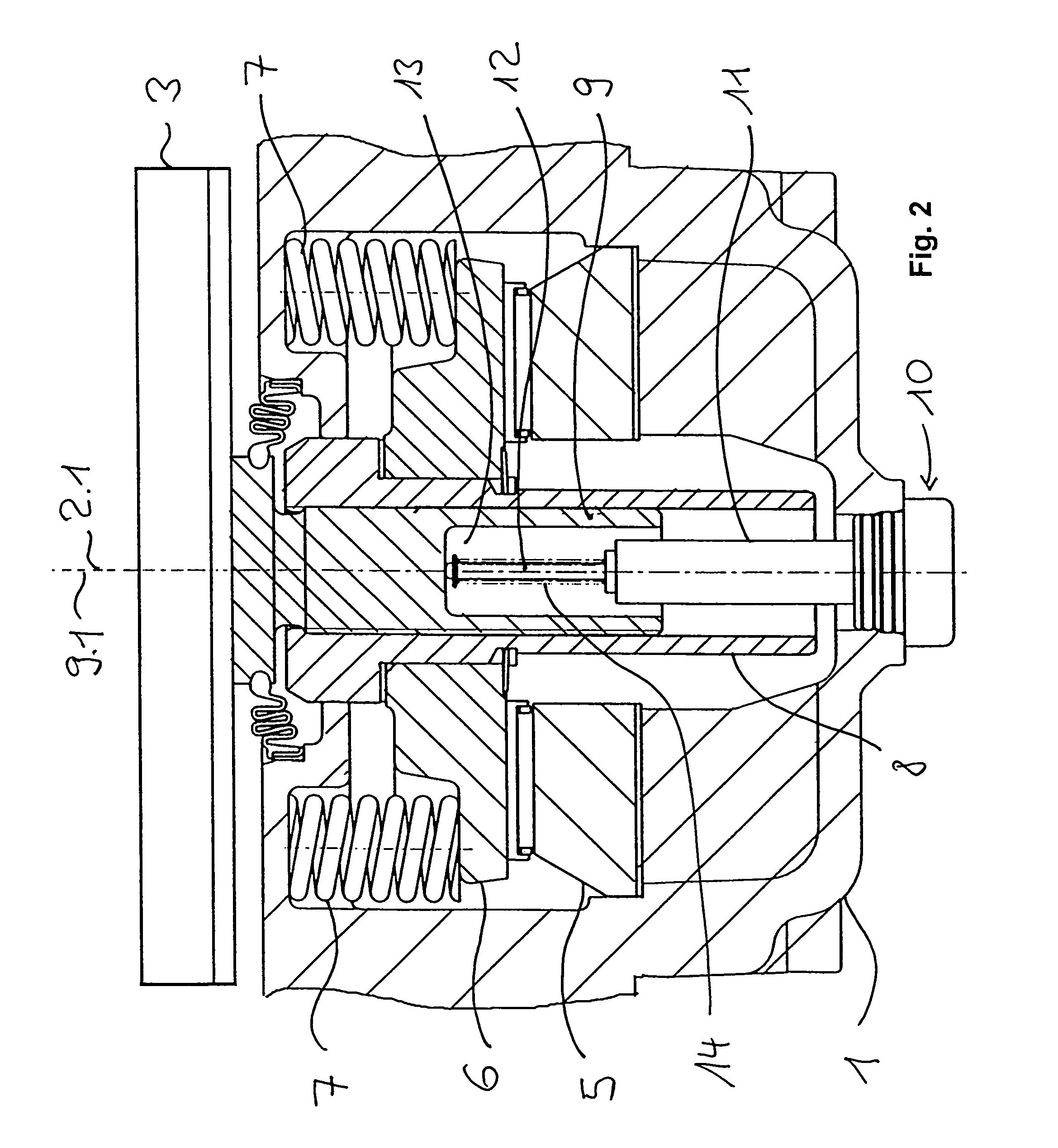
[0026]The disc brakes illustrated in the drawings each have a brake caliper 1 spanning, as is conventional, with its two caliper legs a brake disc 2. At both sides of the brake disc 2 brake pads 3, 4 are provided. The brake caliper 1 itself has at least on one side of the brake disc a brake actuating device that, when actuated, forces the brake pads 3, 4 against the brake disc 2. In the brake caliper 1 a rotary lever 5.1 is provided that is pivotably supported about an axis of rotation extending parallel to the main plane of the brake disc 2. An actuating device, not illustrated in the drawing, engages the free end of the rotary lever 5.1 when the brakes are applied. Pivoting of the rotary lever 5.1 causes a rotation of a brake applicator shaft 5 that is coupled to a thrust member 6. The thrust member 6 extends within the brake caliper 1 parallel to the main plane of the brake disc 2. Upon actuation of the rotary lever 5.1, it is forced in the direction toward the brake disc 2. The ...


PUM


Abstract

A disc brake has a brake disc and a brake caliper spanning the brake disc. A brake applicator shaft is supported on the brake caliper and arranged transversely to an axis of rotation of the brake disc. The brake applicator shaft has a rotary lever for actuating the brake applicator shaft. An adjusting device provided with a thrust spindle having an end face facing away from the brake disc is provided. The brake applicator shaft transmits upon brake application a brake force through the thrust spindle onto the brake disc. A monitoring device is provided that has a measuring element moveable relative to the brake caliper and resting against the end face of the thrust spindle.

Description

BACKGROUND OF THE INVENTION[0001]1. Field of the Invention[0002]The invention relates to a disc brake comprising a brake disc; a brake caliper on which is supported a brake applicator shaft that is actuated by means of a rotary lever and that extends transversely to an axis of rotation of the brake disc; a thrust spindle that belongs to an adjusting device and by means of which upon brake application an application force is transmitted from the brake applicator shaft onto the brake disc; and a monitoring device, in particular, for monitoring wear of the brake, a stroke of the brake, and / or readjustment of the brake.[0003]2. Description of the Related Art[0004]Such a disc brake is disclosed, for example, in European patent application 0 784 162 A2. According to this patent application, a wear sensor 50 and a thrust member 9 form a unitary module, wherein relative movements of the thrust spindles 10, 11 relative to a thrust member are detected by the sensor in that the sensor is conne...

Claims


Application Information

Patent Timeline
Patent Type & Authority Patents(United States)
IPC IPC(8): F16D66/02F16D65/14
CPCF16D65/18F16D65/567F16D66/02F16D2066/003F16D2121/14
Inventor DECKHUT, ANDREASSTUMPF, MARTIN
Owner WABCO EURO BVBA SPRL
Why Eureka
Try Eureka