End mill and a method of operating an end mill

a technology of end mill and end mill, which is applied in the field of end mill and a method of operating an end mill, can solve the problems of low accuracy loss, inability to achieve high metal removal rate, and insufficient torsional and bending stiffness of end mill, so as to achieve the effect of improving rigidity

Active Publication Date: 2008-01-29
KENNAMETAL INC
View PDF6 Cites 8 Cited by
  • Summary
  • Abstract
  • Description
  • Claims
  • Application Information

AI Technical Summary

Benefits of technology

[0013]It is therefore one of the objects of at least one possible embodiment of an end mill described herein to obviate the disadvantages of prior art end mills and to provide a cutter tooth form which has adequate chip clearance flute channels while providing improved torsional rigidity as well as improved bending resistance.SUMMARY
[0020]Thus a shaft or a milling cutter subjected to torque can be stiffened by adding one or more areas to its cross-section to increase its J value.
[0021]Because the value r appears in the formula for calculating J as r2, a very effective method of increasing J is to increase r by positioning the various area components comprising the cross-sectional area as far away from the center of twist as is possible. A simple illustration of this is found when a solid round shaft is replaced by a hollow cylinder or pipe of the same cross-sectional area and of the same weight, resulting in a much stiffer shaft due to the higher J value of the cylinder.
[0023]While the extra areas on the rear face of the end mill teeth serve primarily to reduce torsional deflection while cutting, the additional benefit offered by the new design is in improved resistance to cantilever-type bending of the cutter when held by the machine at the shank end and pressed against the work-piece at the cutting end. As is well known, improved rigidity of the cutter improves the machined surface finish, improves the ability to machine to close tolerances, and with regard to roughing increases the possible metal removal rate, doing so while generating less vibration and less noise.
[0024]It will thus be realized that the cutting tool according to at least one possible embodiment serves to increase the J value essentially without reducing the size of the flute. By maintaining flute size, the flow of coolant to the cutting edges is not disturbed, and, more significantly, the discharge of chips from the cutting area through the flutes is virtually unobstructed.

Problems solved by technology

End mills are widely used in milling operations due to their versatile range of application and due to the moderate first cost of the tool.
The smaller core diameter may lead to minor loss of accuracy due to tool bending under pressure, but this is of little concern for roughing operations.
An end mill with inadequate torsional and bending stiffness will vibrate angularly with high amplitude and not achieve high metal removal rates.
Attempts to make deep cuts at high feed rates are liable to result in poor accuracy and surface quality, noise, and early breakage of the cutter.

Method used


Image

  • End mill and a method of operating an end mill
  • End mill and a method of operating an end mill
  • End mill and a method of operating an end mill

Examples


Embodiment Construction

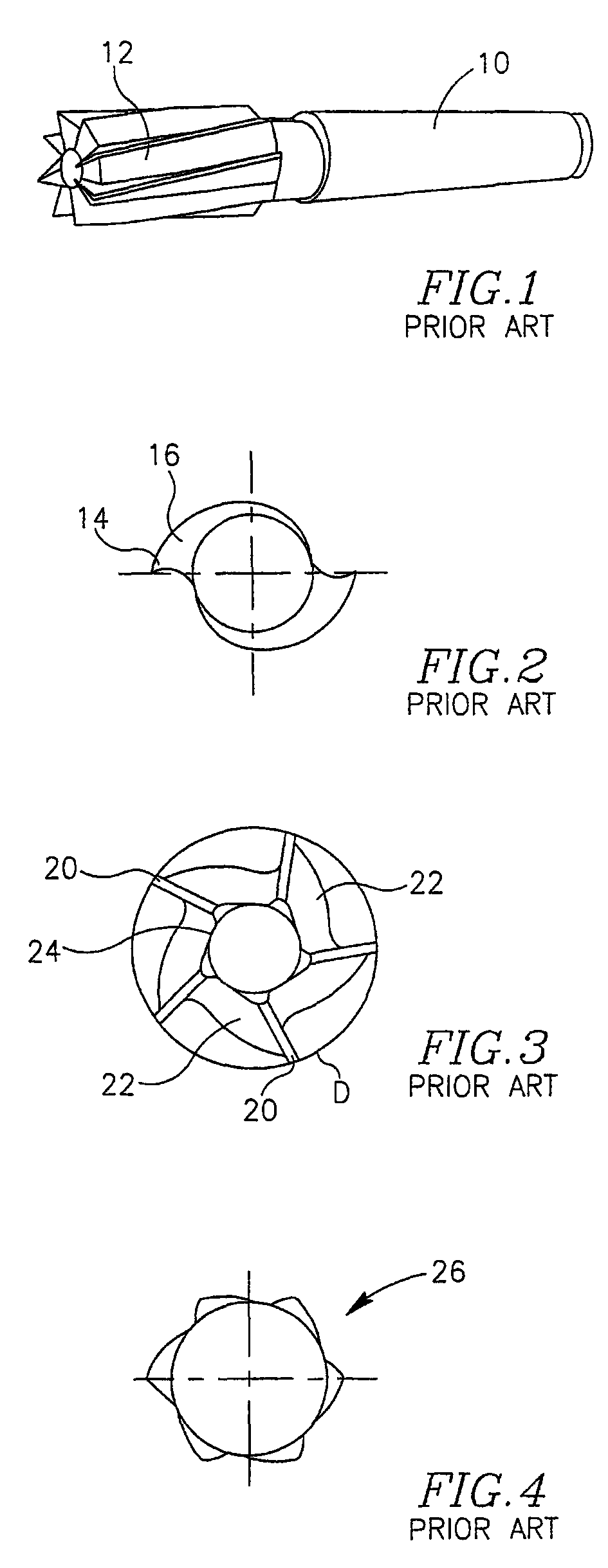
[0038]There is seen in FIG. 1 a prior art end mill having a shank or body portion 10 and a cutting portion 12. The end mill seen has 8 teeth and an outside diameter large enough (about 50-80 mm diameter) to allow chip clearance between teeth.

[0039]The prior art cutter seen in FIG. 2 has two teeth 14, each tooth having a backing portion 16 which recedes to the core diameter 18 over about 160°. The C value is about 0.58.

[0040]The prior art end mill seen in FIG. 3 has 5 teeth 20, each having a backing portion 22 which recedes to a position about halfway between the core diameter 24 and the outside diameter D.

[0041]FIG. 4 illustrates a prior art 6-tooth cutter 26. The tooth form 28 has a negative rake as it is intended to machine highly hardened steels, such as more than 55HRc steels (on the Rockwell scale of hardness), the tool 28 being made of sintered carbide.

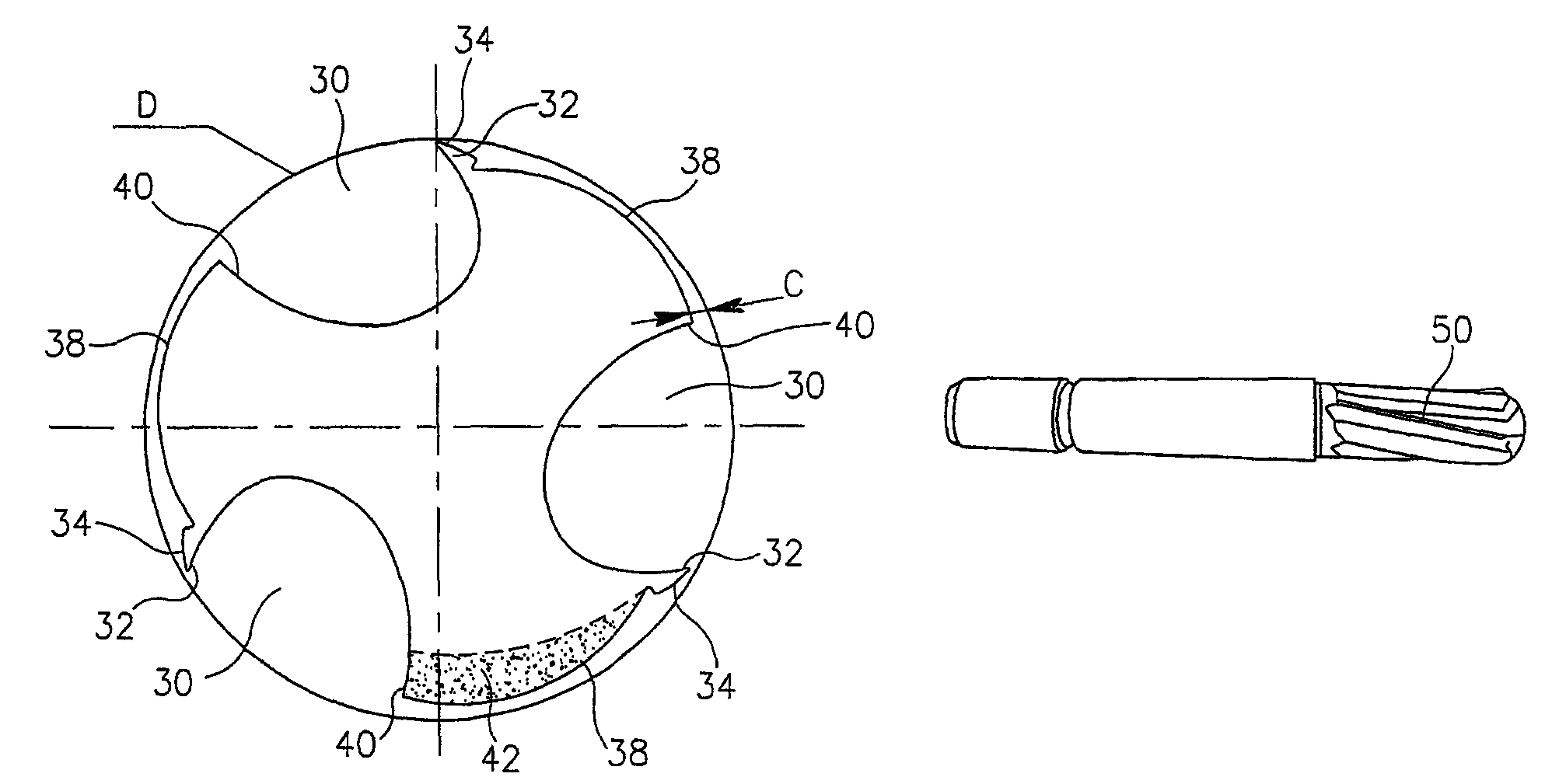
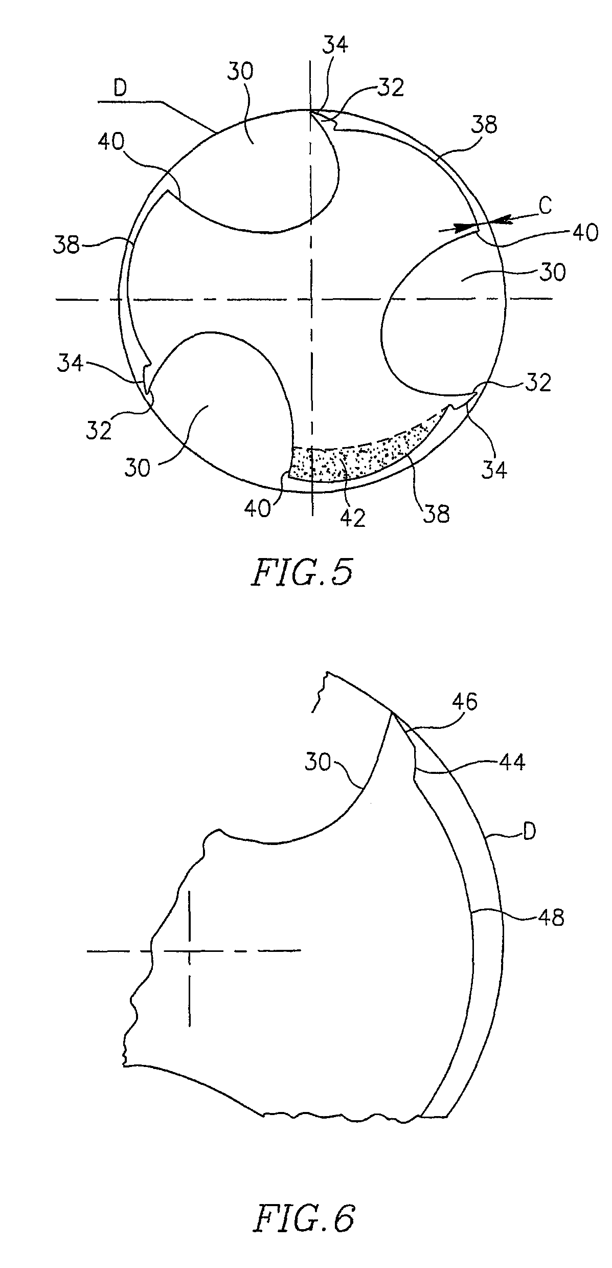
[0042]Turning now to FIG. 5, there is depicted a 3-tooth end mill configured for improved rigidity according to the present in...


PUM

PropertyMeasurementUnit
diameteraaaaaaaaaa
diameteraaaaaaaaaa
diameteraaaaaaaaaa

Abstract

An end mill for cutting or milling objects and a method of operation thereof. The abstract of the disclosure is submitted herewith as required by 37 C.F.R. §1.72(b). As stated in 37 C.F.R. §1.72(b): A brief abstract of the technical disclosure in the specification must commence on a separate sheet, preferably following the claims, under the heading “Abstract of the Disclosure.” The purpose of the abstract is to enable the Patent and Trademark Office and the public generally to determine quickly from a cursory inspection the nature and gist of the technical disclosure. The abstract shall not be used for interpreting the scope of the claims. Therefore, any statements made relating to the abstract are not intended to limit the claims in any manner and should not be interpreted as limiting the claims in any manner.

Description

CONTINUING APPLICATION DATA[0001]This application is a Continuation-In-Part application of International Patent Application No. PCT / IL2005 / 000628, filed on Jun. 15, 2005, which claims priority from Israeli Patent Application No. 162587, filed on Jun. 17, 2004. International Patent Application No. PCT / IL2005 / 000628 was pending as of the filing date of this application. The United States was an elected state in International Patent Application No. PCT / IL2005 / 000628.BACKGROUND[0002]1. Technical Field[0003]This application relates to tools, such as end mills, for the milling of materials. This application further relates to at least one possible embodiment that provides improved torsional and bending rigidity of a tool's body in an end mill, thereby to extend tool life while making possible machining at increased metal removal rates, and better surface quality, while minimizing vibration.[0004]2. Background Information[0005]End mills are widely used in milling operations due to their ve...

Claims


Application Information

Patent Timeline
Patent Type & Authority Patents(United States)
IPC IPC(8): B23C5/10B23CB23C5/00
CPCB23C5/003B23C5/10B23C2210/0442B23C2210/54B23C2220/605Y10T407/196B23C2222/32B23C2226/18Y10T407/1946Y10T407/1966B23C2222/16
Inventor VOLOKH, VLADIMIR
Owner KENNAMETAL INC
Why Eureka
Try Eureka