
Doorway-mounted exercise device with resistance bands

a technology of resistance bands and exercise devices, which is applied in the direction of resistance force resistors, gymnastics exercise, therapy exercise, etc., can solve the problems of limiting the number of exercises that can be performed while standing on resistance bands, affecting so as to reduce the overall length of the main tube. , the effect of increasing the overall length of the main tub

Inactive Publication Date: 2008-01-29
LOCCARINI DARIN A +1
View PDF6 Cites 69 Cited by
  • Summary
  • Abstract
  • Description
  • Claims
  • Application Information

AI Technical Summary

Benefits of technology

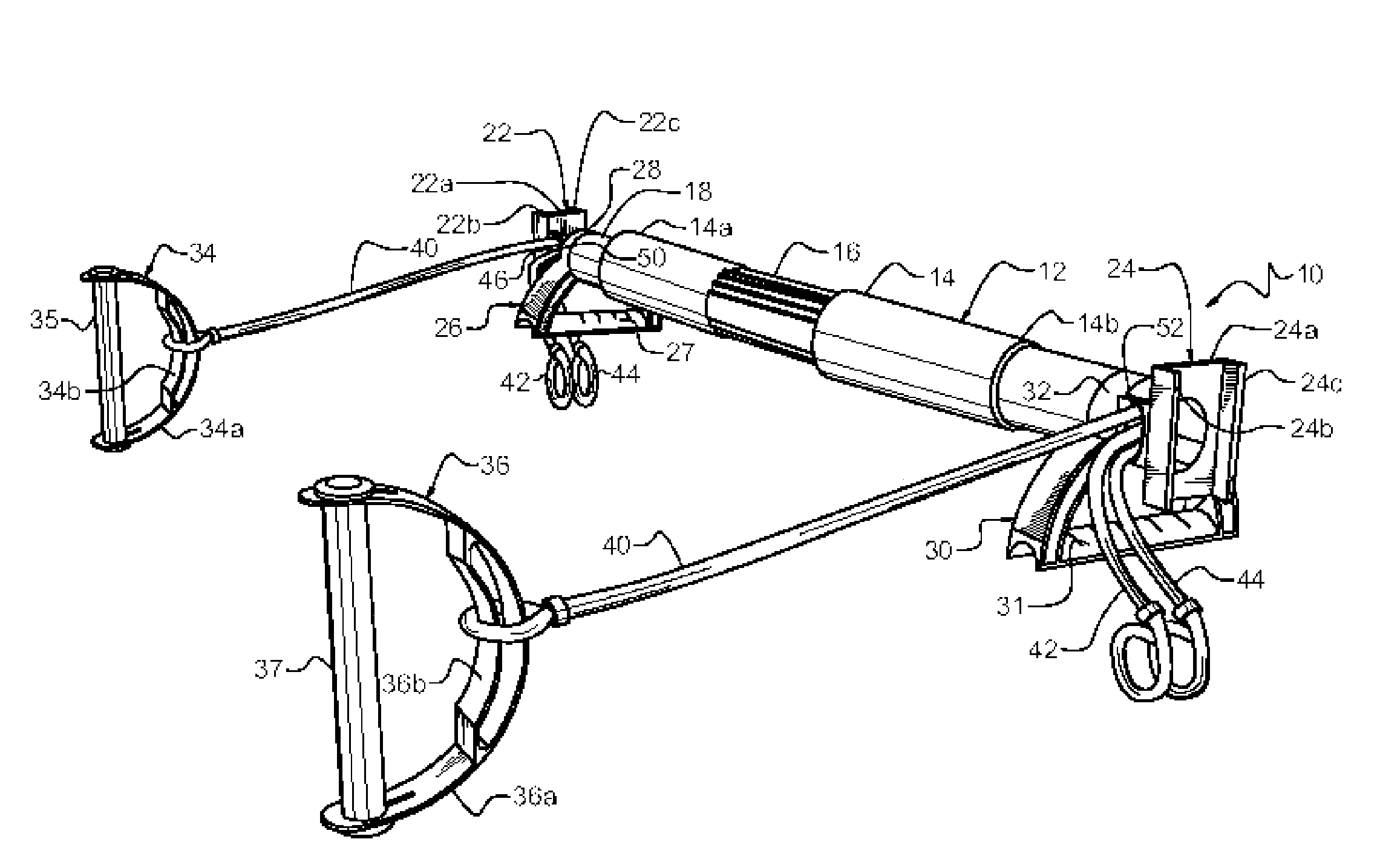
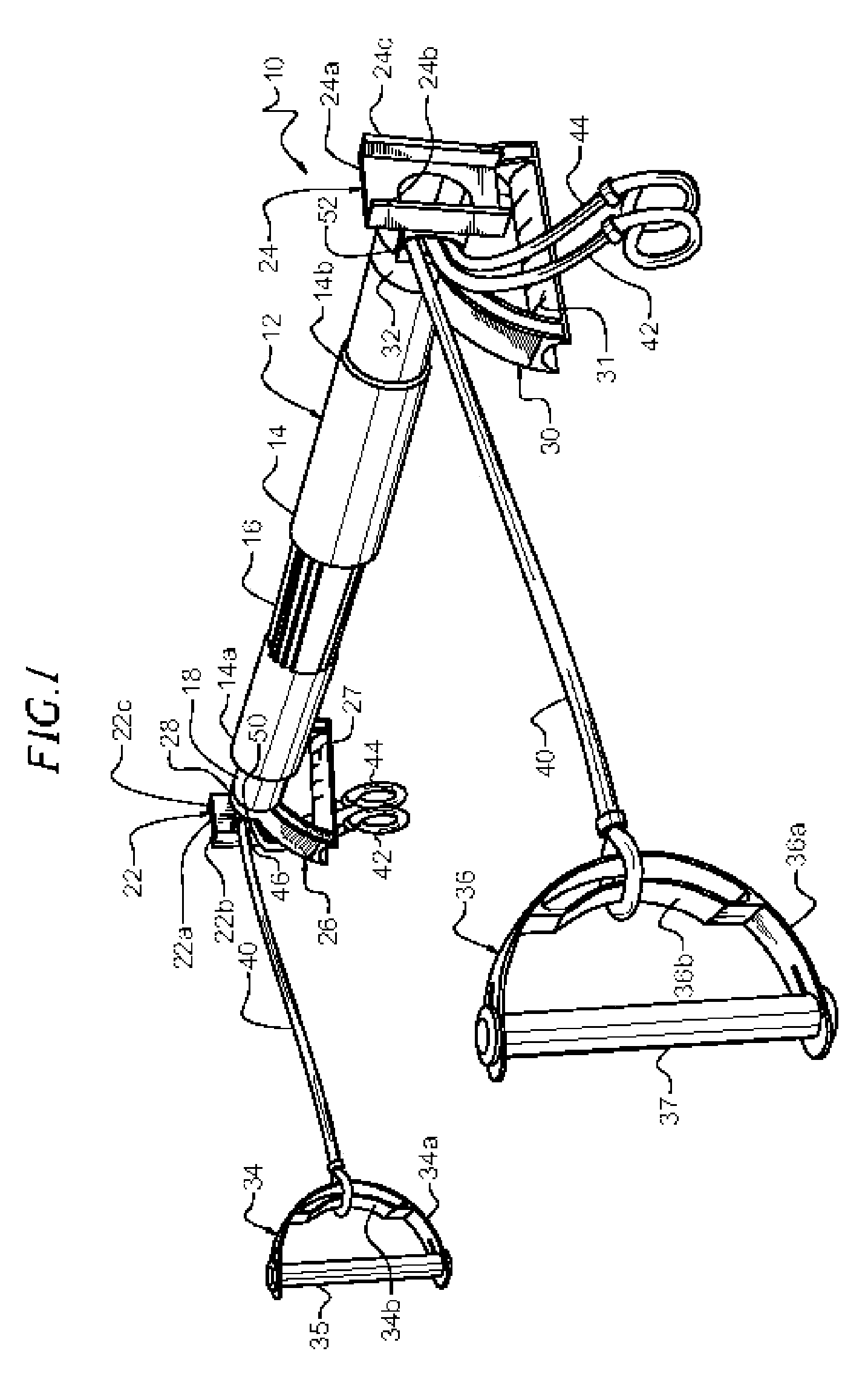
[0011]The long-standing but heretofore unfulfilled need for a means for a resistance band exercise device that enables the performance of a large plurality of exercises is now met by a new, useful, and non-obvious invention. The novel portable exercise device includes a main tube having an adjustable length. The main tube includes a central tube, a first outboard tube connected to a first end of the central tube and a second outboard tube connected to a second end of the central tube. The central tube screwthreadedly engages the first outboard tube and the second outboard tube so that rotation of the central tube in a first direction causes the first and second outboard tubes to travel away from one another, thereby increasing an overall length of the main tube and so that rotation of the central tube in a second direction opposite to the first direction causes the first and second outboard tubes to travel toward one another, thereby decreasing the overall length of the main tube. A first handle is rotatably secured to the first outboard tube and a second handle is rotatably secured to the second outboard tube.

Problems solved by technology

The number of exercises that can be performed while standing on resistance bands is limited.
This positions the resistance bands in a “V”-shaped configuration and makes the exercises somewhat unbalanced or unstable.
This limits the number of exercises that can be performed.
Another drawback is that the known resistance bands exercise devices present only one level of resistance.
Thus, as the exerciser becomes more conditioned, exercising with the same bands provides less and less benefit.

Method used


Image

  • Doorway-mounted exercise device with resistance bands
  • Doorway-mounted exercise device with resistance bands
  • Doorway-mounted exercise device with resistance bands

Examples


Embodiment Construction

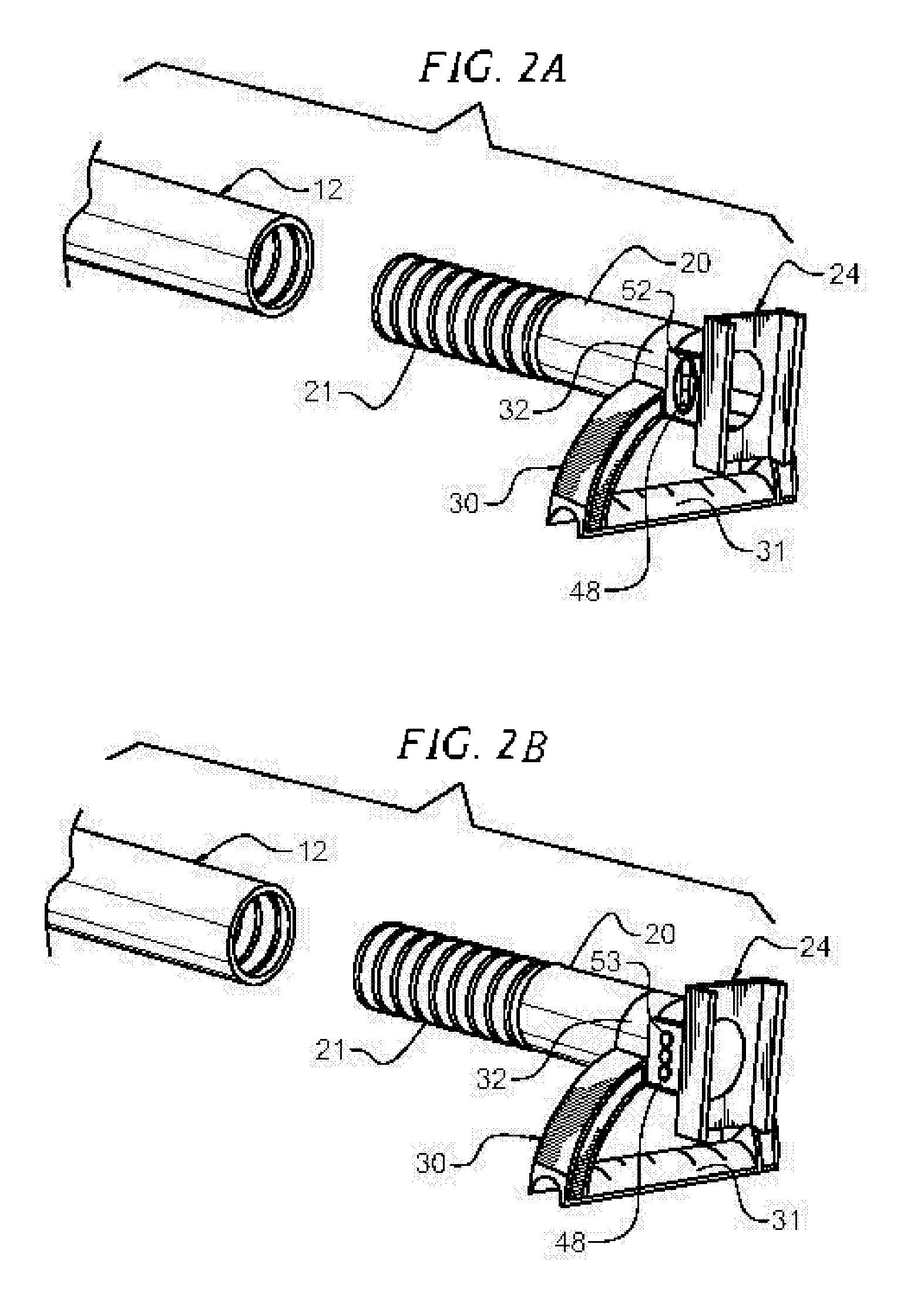
[0031]Referring now to FIGS. 1 and 2A, it will there be seen that an illustrative embodiment of the invention is denoted as a whole by the reference numeral 10.

[0032]Adjustable tube 12 has three (3) primary parts. Central tube 14 is hollow and has opposite ends 14a and 14b that are internally threaded in opposite directions. Thus, left end 14a may have left-hand internal threads formed therein and right end 14b may have right-hand internal threads formed therein, or vice versa.

[0033]Grip member 16 ensleeves central tube 14 and is located mid-length thereof. Grip member 16 is secured to central part 14 so that rotation of grip member 16 about its longitudinal axis of symmetry effects simultaneous and corresponding, i.e., conjoint rotation of central tube 14.

[0034]The two (2) remaining primary parts of adjustable tube 12 are externally threaded left or first outboard tube 18 and externally threaded right or second outboard tube 20. Only the respective inboard ends of outboard tubes 18...


PUM


Abstract

A portable exercise device includes a main tube having an adjustable length. The main tube includes a central tube and an outboard tube connected to opposite ends of the central tube. First and second door jamb gripping devices adapted to engage a door stop of a door jamb are secured to respective outermost ends of the outboard tubes. A handle is secured to each outboard tube and a pulley is mounted within a hollow interior of each outboard tube. A first resistance band has a first end engaged to a third handle, a second end engaged to a fourth handle, and a medial part positioned in a hollow interior of the main tube that engages the first and second pulleys.

Description

FIELD OF THE INVENTION[0001]This invention relates, generally, to portable exercise devices. More particularly, it relates to an exercise device that can be mounted at any height in a doorway and which includes resistance bands so that it may be used in scores of exercises.DESCRIPTION OF THE PRIOR ART[0002]Resistance bands generally require a user to stand on the bands during the exercise period. The number of exercises that can be performed while standing on resistance bands is limited.[0003]There is a need, therefore, for a resistance band-reliant exercise device that does not require a user to stand on it.[0004]Some devices require a user to clamp one end of a resistance device to a door or door knob and to exercise by pulling on the other end. This positions the resistance bands in a “V”-shaped configuration and makes the exercises somewhat unbalanced or unstable. Modern fitness club machines and weights, on the other hand, provide resistances that are in line with the trajector...

Claims


Application Information

Patent Timeline
Patent Type & Authority Patents(United States)
IPC IPC(8): A63B21/04A63B21/02
CPCA63B17/00A63B21/055A63B21/0552A63B21/1423A63B21/1627A63B21/00065A63B21/0428A63B21/0557A63B2210/50Y10S482/904A63B21/4011
Inventor LOCCARINI, DARIN A.LYTELL, MATTHEW B.
Owner LOCCARINI DARIN A
Learn More