
Vacuuming machine

a vacuuming machine and vacuuming filter technology, applied in the field of vacuuming machines, can solve problems such as debris clogging, reduce air speed, reduce or eliminate the need to clean the filters within the vacuuming machine, and reduce the effect of exhaust debris

Inactive Publication Date: 2008-01-29
BAUTE HOBERT RONALD +1
View PDF30 Cites 20 Cited by
  • Summary
  • Abstract
  • Description
  • Claims
  • Application Information

AI Technical Summary

Benefits of technology

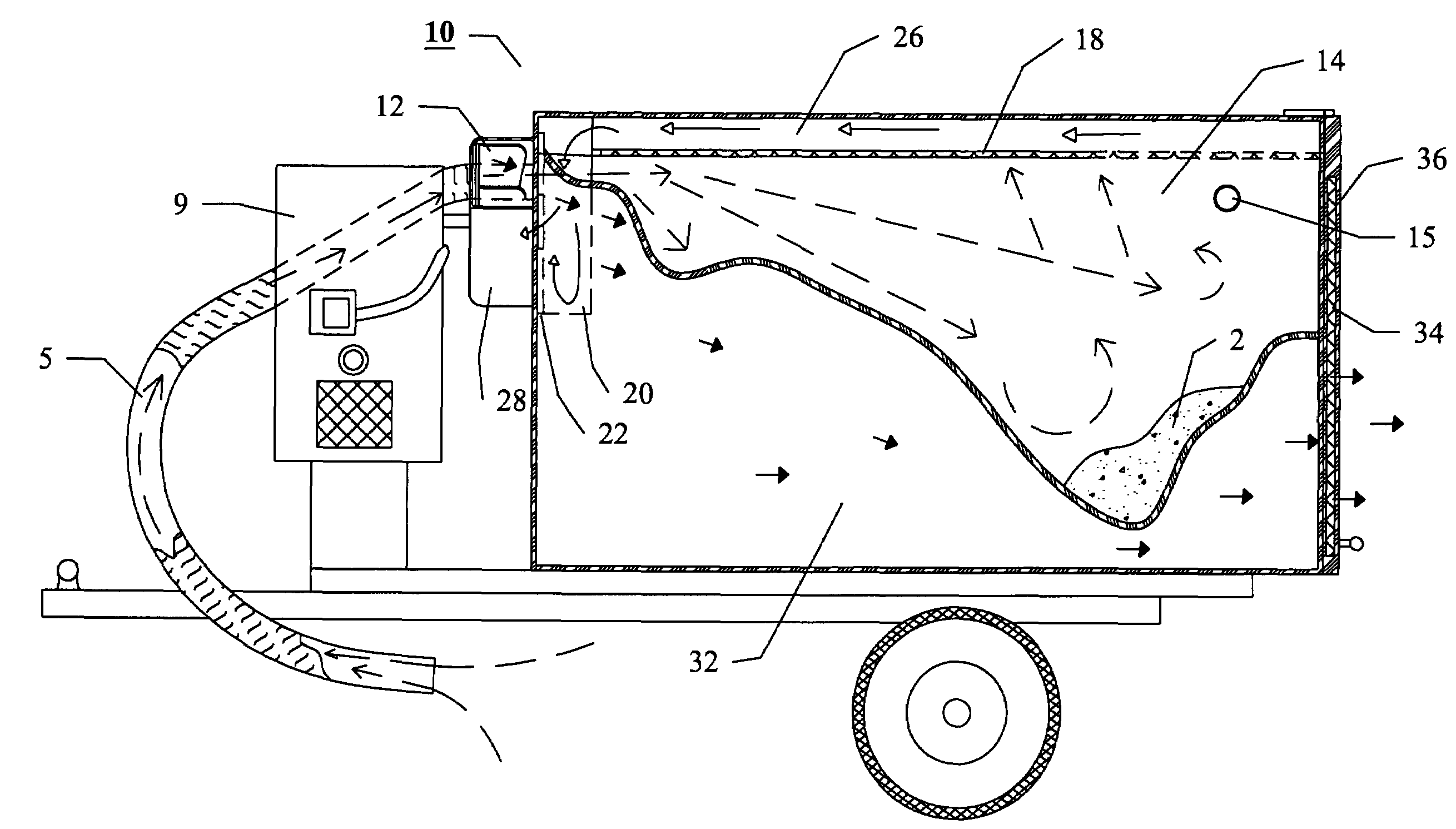
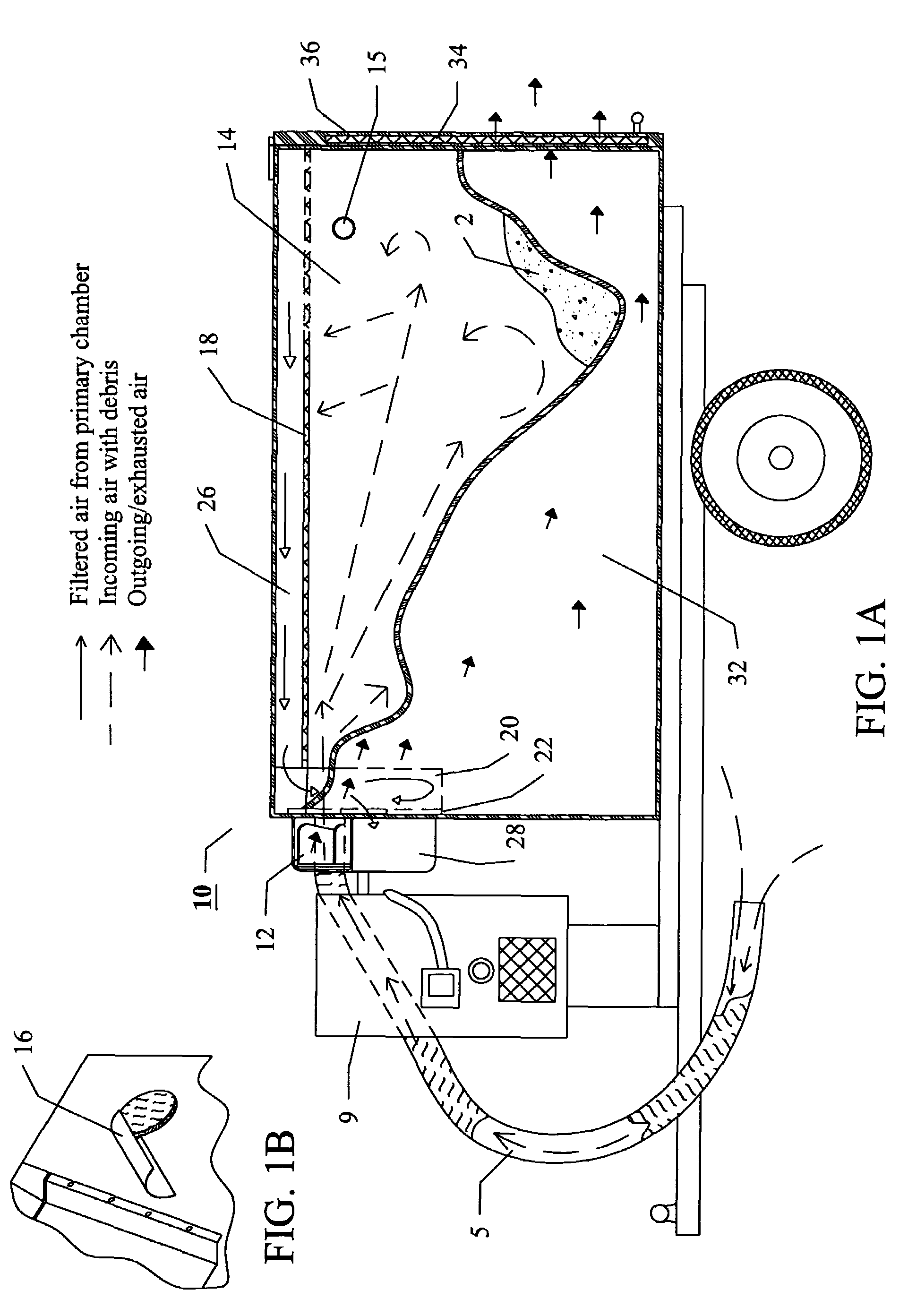
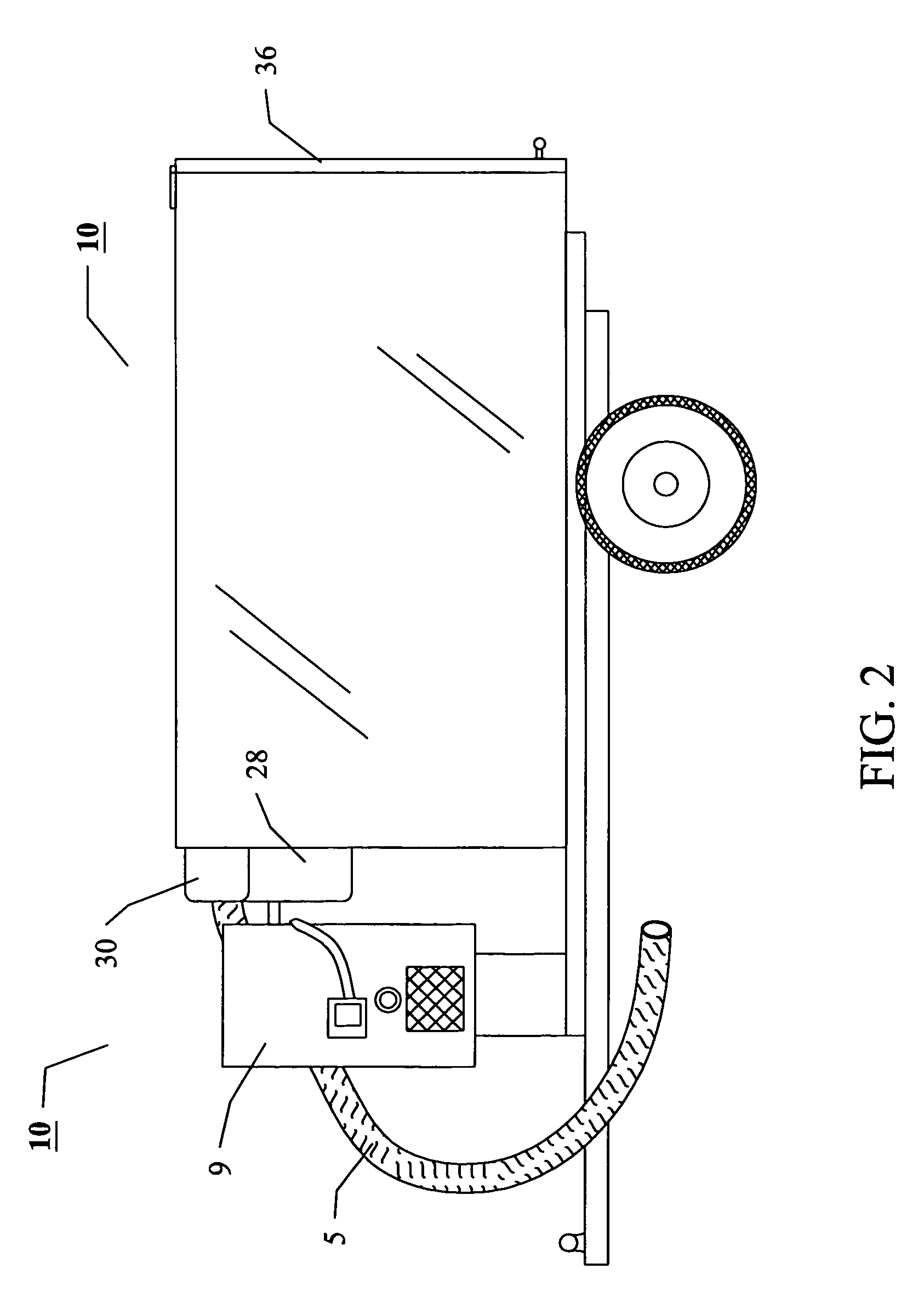
[0002]The subject invention pertains to a vacuuming machine particularly useful for industrial or farm waste. The invention is ideally suited for cleaning animal stalls, particularly animal wastes, hay, and other organic or non-organic debris. The system of filters and exhaust in the subject invention can reduce or eliminate exhaust debris and can also reduce or eliminate the need to clean the filters within the machine. The subject vacuuming machine utilizes a fan to create a vacuum within a primary chamber. By attaching a hose, tube, or pipe to the primary chamber the vacuum within the chamber allows debris to be moved or “sucked” up by the hose, tube, or pipe. The debris moves rapidly through the hose, tube, or pipe until it reaches the primary chamber. At that point, the reduction in air speed which occurs when the air and debris enter the primary chamber allows debris to be deposited onto the floor of the primary chamber. The air within the primary chamber is drawn through a grid-like filter located in the upper portion of the primary chamber and into a filter duct that can lead to a smaller filter hopper before exiting through an opening in a fan plate leading to the fan. Because the air flowing through the filter duct is moving into the smaller area of the filter hopper, the air flow is again increased. This increase in air flow ensures that any debris which comes through the filter and the duct remains suspended as the exhausted air is moved by the blades of the fan into an connection duct which leads into a secondary chamber. The air coming through the connection duct, moving at increased speed enters the secondary chamber. Once the exhausted air moves into the secondary chamber, which is a larger volume than the connection duct, the air slows down allowing any particulate matter carried through the fan and the connection duct to be deposited on the floor of the secondary chamber. The slower moving exhausted air in the secondary chamber can then move through an exhaust filter as it exits the vacuuming machine. This dual gravity-dependent filtering process provides exemplary vacuuming power and exhausted air that is relatively free of debris.

Problems solved by technology

However, a universal problem with most of these filtering systems is that they become clogged with debris.

Method used


Image

  • Vacuuming machine
  • Vacuuming machine
  • Vacuuming machine

Examples


Embodiment Construction

[0017]The subject invention provides an improved vacuuming machine that in a preferred embodiment is particularly suited for industrial or farm use. However, it is possible for the device of the subject invention to be scaled for home or other indoor use. The subject invention is suited for vacuuming a variety of materials, including solids, semi-solids, liquids, or combinations thereof. A particular advantage of the device of the subject invention is its filtering system. The configuration of the filtering system of the device does not lend itself to being easily clogged or blocked with debris. In fact, when the vacuuming machine is properly calibrated, most incoming debris will not reach the filters until the device has reached approximately 70% to about 80% capacity.

[0018]The design of the vacuum machine makes it ideally suited for large industrial site cleaning or field or yard use. It is particularly suited for cleaning animal stalls or cages, particularly horse stalls. The sub...


PUM

PropertyMeasurementUnit
diameteraaaaaaaaaa
diameteraaaaaaaaaa
diameteraaaaaaaaaa

Abstract

The subject invention pertains to a vacuuming machine with a primary chamber in which vacuum pressure within allows the ingress of debris through a hose. Air and debris entering the primary chamber decelerate upon entry into the chamber which allows debris to settle out of the air column within the primary chamber. Air within the primary chamber is evacuated through an enlarged filter and duct system that carries the air through a filter hopper and fan plate to a rotating fan. The blades of the fan move air and particulate matter through a second duct into a secondary chamber in which another deceleration of air and debris allows additional debris to settle to the bottom of the secondary chamber before air is finally evacuated from the vacuum machine.

Description

BACKGROUND OF INVENTION[0001]The present invention is directed to an all-purpose vacuuming machine suited for industrial or farm use. The subject invention can vacuum various types, sizes, and weights of matter which is then deposited into collection chambers. Most vacuums utilize various types of filters to prevent debris from exiting the device with the exhausted air. However, a universal problem with most of these filtering systems is that they become clogged with debris. The subject invention addresses this issue with a unique filtering system within the device that is less prone to clogging and allows for the exhausting of relatively clean air.BRIEF SUMMARY OF THE INVENTION[0002]The subject invention pertains to a vacuuming machine particularly useful for industrial or farm waste. The invention is ideally suited for cleaning animal stalls, particularly animal wastes, hay, and other organic or non-organic debris. The system of filters and exhaust in the subject invention can red...

Claims


Application Information

Patent Timeline
Patent Type & Authority Patents(United States)
IPC IPC(8): B01D46/00
CPCA01D43/077E01H1/0836B01D2273/28Y10S55/03
Inventor REDLIN, WILLIAM L
Owner BAUTE HOBERT RONALD
Learn More