Fuel cell system and method of operation to reduce parasitic load of fuel cell peripherals

a fuel cell and peripheral technology, applied in the field of fuel cell systems, can solve the problems of reducing the operating life and operational and achieve the effect of reducing the parasitic load and operating efficiency of the fuel cell system

Active Publication Date: 2008-01-29
HYDROGENICS CORP
View PDF10 Cites 8 Cited by
  • Summary
  • Abstract
  • Description
  • Claims
  • Application Information

AI Technical Summary

Problems solved by technology

That is, if the operating level of a fuel cell system increases significantly without a concomitant increase in the above-mentioned operational parameters, then contaminants will build up in the system, resulting in a decrease in both operational efficiency and in the operating lifetime of the fuel cell system.

Method used


Image

  • Fuel cell system and method of operation to reduce parasitic load of fuel cell peripherals
  • Fuel cell system and method of operation to reduce parasitic load of fuel cell peripherals
  • Fuel cell system and method of operation to reduce parasitic load of fuel cell peripherals

Examples


Embodiment Construction

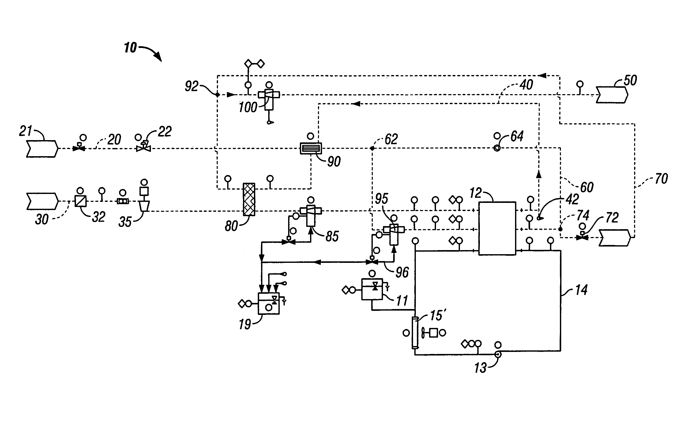
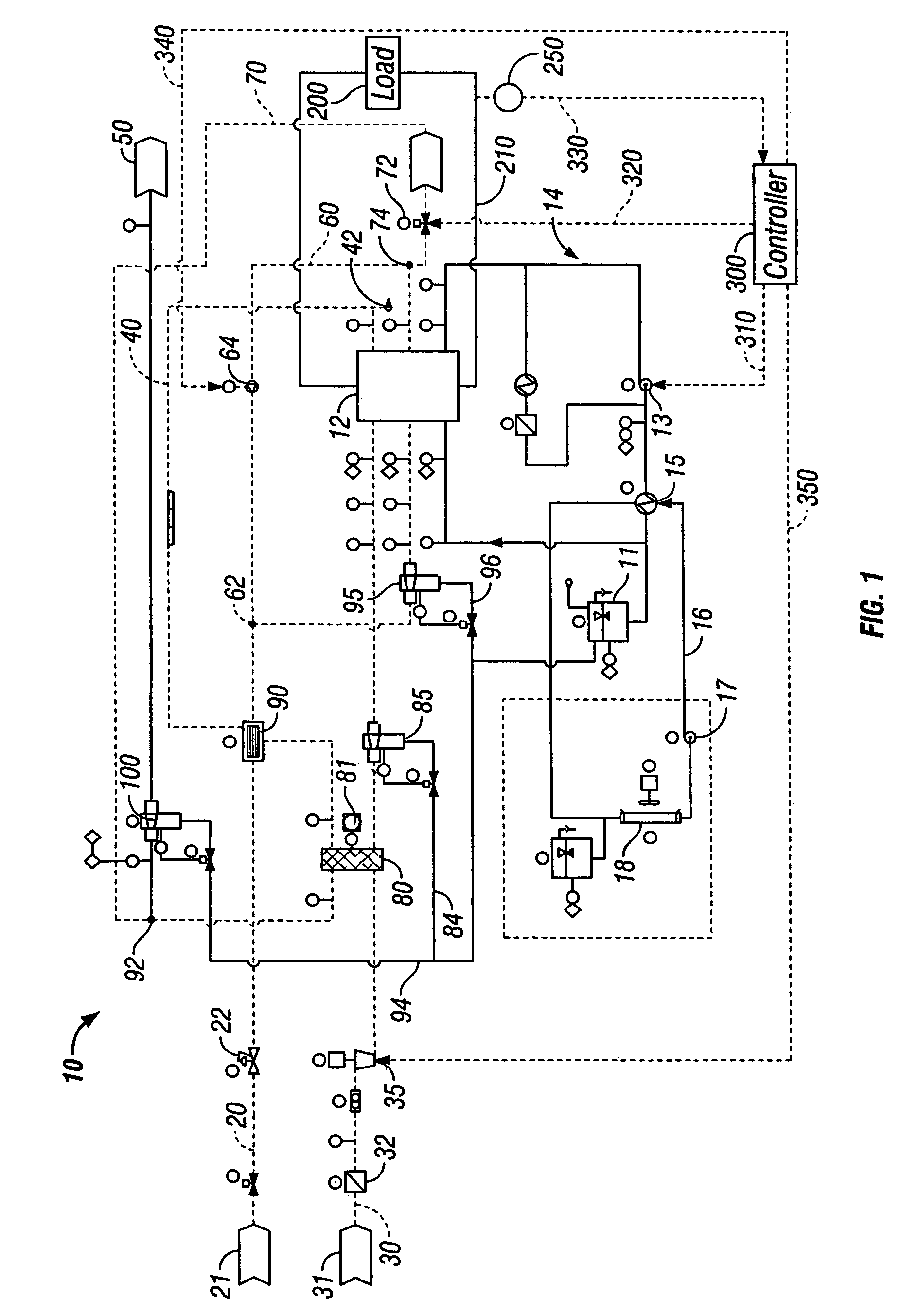
[0021]Referring first to FIG. 1, there is illustrated a schematic flow diagram of a first embodiment of a fuel cell gas management system 10 according to the present invention. The fuel cell gas management system 10 comprises a fuel supply line 20, an oxidant supply line 30, a cathode exhaust recirculation line 40 and an anode exhaust recirculation line 60, all connected to a fuel cell 12. It is to be understood that the fuel cell 12 may comprise a plurality of fuel cells or just a single fuel cell. For simplicity, the fuel cell 12 described herein operates on hydrogen as fuel and air as oxidant and can be a Proton Exchange Membrane (PEM) fuel cell. However, the present invention is not limited to this type of fuel cells and is applicable to other types of fuel cells that rely on other fuels and oxidants.

[0022]The fuel supply line 20 is connected to a fuel source 21 for supplying hydrogen to the anode of the fuel cell 12. A hydrogen humidifier 90 is disposed in the fuel supply line ...


PUM

PropertyMeasurementUnit
current densityaaaaaaaaaa
poweraaaaaaaaaa
current densityaaaaaaaaaa

Abstract

A fuel cell system and a method of operating same are provided. The fuel cell system includes a fuel cell for driving a load, at least one fuel cell peripheral, a device for measuring at least one fuel cell operation characteristic, and at least one controller for controlling the operation of at least one fuel cell peripheral based on the at least one fuel cell operation characteristic. The fuel cell operation characteristic is divided into at least two ranges, and operation of at least one fuel cell is controlled to provide it with a respective operational characteristic for each range of operation of the fuel cell system.

Description

FIELD OF THE INVENTION[0001]The present invention relates generally to a fuel cell system. More particularly, the present invention relates to a method of operating a fuel cell system to minimize parasitic load.BACKGROUND OF THE INVENTION[0002]Fuel cell systems are seen as a promising alternative to traditional power generation technologies due to their low emissions, high efficiency and ease of operation. Fuel cells operate to convert chemical energy into electrical energy. Proton exchange membrane fuel cells comprise an anode, a cathode, and a selective electrolytic membrane disposed between the two electrodes. In a catalyzed reaction, a fuel such as hydrogen, is oxidized at the anode to form cations (protons) and electrons. The ion exchange membrane facilitates the migration of protons from the anode to the cathode. The electrons cannot pass through the membrane and are forced to flow through an external circuit thus providing an electrical current. At the cathode, oxygen reacts ...

Claims


Application Information

Patent Timeline
Patent Type & Authority Patents(United States)
IPC IPC(8): H01M8/04H01M8/00
CPCH01M8/04029H01M8/04097H01M8/04141H01M8/04164H01M8/04328H01M8/04335H01M8/04492H01M8/04589H01M8/04619H01M8/04753H01M8/04761H01M8/04768Y02E60/50
Inventor CARGNELLI, JOSEPHSIMPSON, TODD A.BURANY, STEPHEN
Owner HYDROGENICS CORP
Why Eureka
Try Eureka