
Method for increasing efficiency of thermotunnel devices

a technology of thermotunnel and thermionic device, which is applied in the direction of sustainable buildings, light and heating apparatus, machine operation mode, etc., can solve the problems of negative heat flow and low heat pumping efficiency

Active Publication Date: 2008-01-29
BOREALIS TECH LTD
View PDF8 Cites 4 Cited by
  • Summary
  • Abstract
  • Description
  • Claims
  • Application Information

AI Technical Summary

Benefits of technology

The present invention is a device and method for enhancing the tunneling of higher energy electrons from an emitter electrode to a collector electrode. This is achieved by modifying the collector electrode to allow for better contact with the emitter electrode, and by adding an insulator layer between the collector electrode and the emitter electrode. The invention also includes a cooling method that involves applying a bias voltage to the emitter electrode, placing a distance between the emitter electrode and the collector electrode, and contacting the insulator layer and the collector layer to cool the emitter electrode. The technical effect of the invention is to improve the efficiency of tunneling and to enhance the cooling of the emitter electrode.

Problems solved by technology

Tunneling of low energy electrons leads to low efficiency heat pumping.
Besides that in some cases tunneling of low energy electron might cause negative heat flow.

Method used


Image

  • Method for increasing efficiency of thermotunnel devices
  • Method for increasing efficiency of thermotunnel devices
  • Method for increasing efficiency of thermotunnel devices

Examples


Embodiment Construction

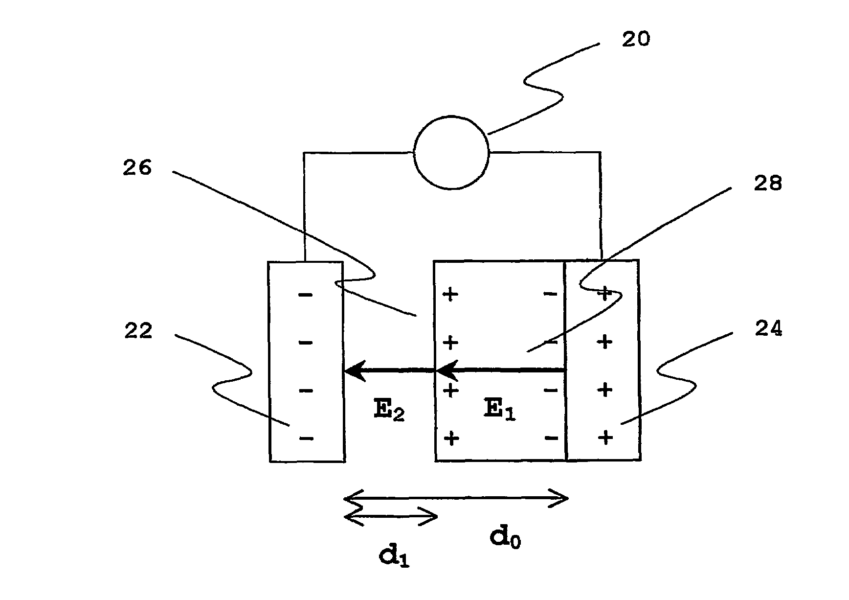
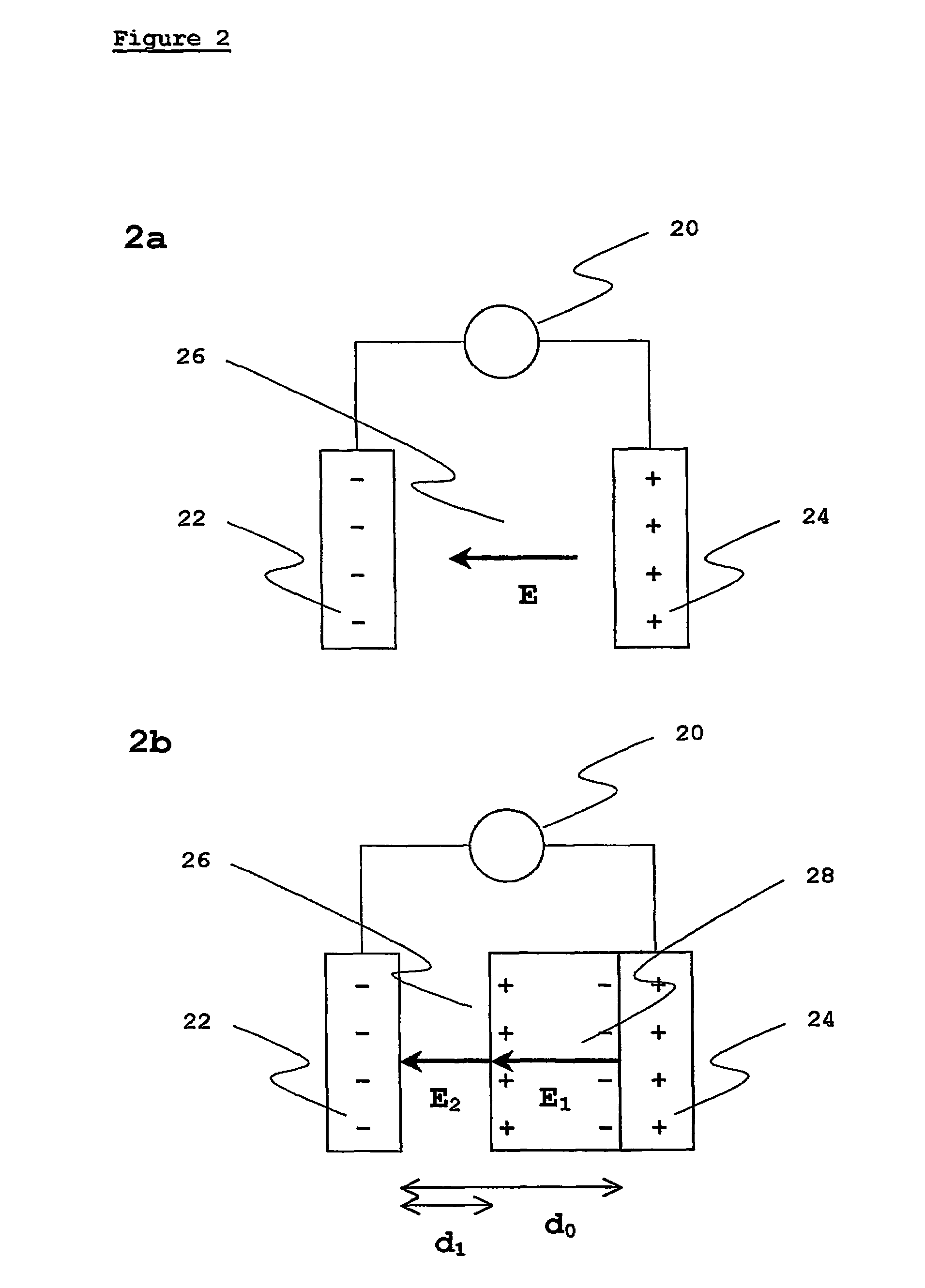
[0013]Embodiments of the present invention and their technical advantages may be better understood by referring to FIGS. 2 and 3.

[0014]It is well known that when an electric field E is applied to an insulator it causes polarization of the insulator atoms and the resulting field is decreased inside the insulator. Thus the field inside the insulator, E1 is equal to E / ε, where s is the dielectric constant of the insulator.

[0015]Referring now to FIG. 2a, which shows a prior art tunneling device, an emitter electrode 22 and a collector electrode 24 are separated by a vacuum gap. Upon application of an external voltage 20, Vbias, the field in the vacuum area between the electrodes is E.

[0016]Referring now to FIG. 3a, which shows the relationship between potential energy E and electrode separation X for the two electrodes of FIG. 2a, high energy electrons 32 and low energy electrons 34 are able to tunnel across the energy barrier. The high energy electrons have to overcome a thinner barrie...


PUM


Abstract

The present invention comprises a tunneling device in which the collector electrode is modified so that tunneling of higher energy electrons from the emitter electrode to the collector electrode is enhanced. In one embodiment, the collector electrode is contacted with an insulator layer, preferably aluminum oxide, disposed between the collector and emitter electrodes. The present invention additionally comprises a method for enhancing tunneling of higher energy electrons from an emitter electrode to a collector electrode, the method comprising the step of contacting the collector electrode with an insulator, preferably aluminum oxide, and placing the insulator between the collector electrode and the emitter electrode.

Description

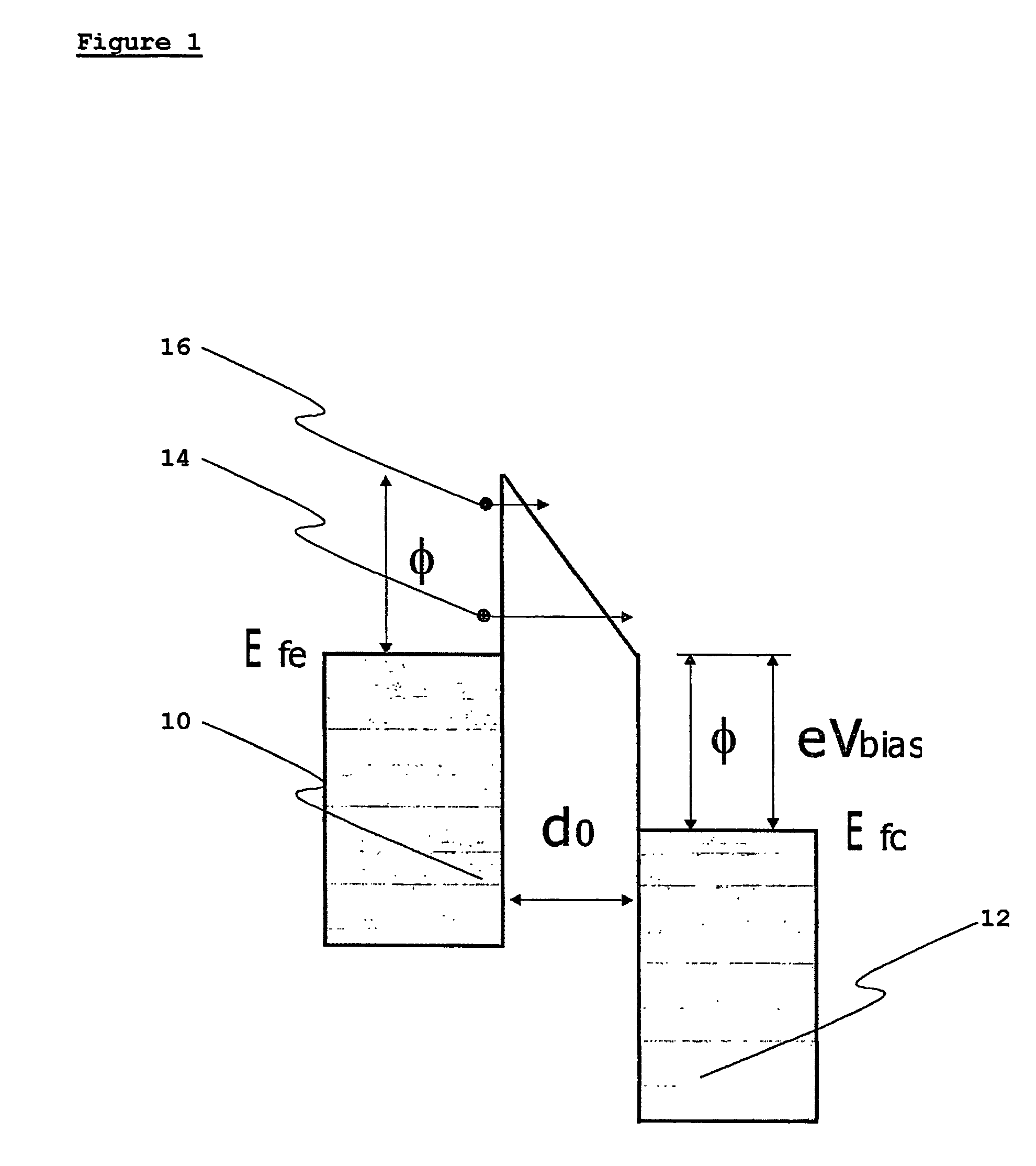
[0001]This application is the U.S. national stage application of International Application PCT / IB2003 / 006484, filed Nov. 27, 2003, which international application was published on Jun. 10, 2004, as International Publication WO2004 / 049379 in the English language. The International Application claims the benefit of U.K. Application No. GB0227687.1, filed Nov. 27, 2002.TECHNICAL FIELD[0002]This invention relates to thermotunneling and thermionic devices.BACKGROUND ART[0003]Simple thermotunnel device comprising two metallic electrodes separated by vacuum gap has energy diagram shown in FIG. 1 (image charge modification of the barrier shape is omitted for simplicity). 10 and 12 are metallic electrodes separated by a distance d0 in a vacuum (U.S. Pat. No. 6,417,060; WO99 / 13562). The cooling power and efficiency of such devices have been calculated by Hishinuma et al. [Appl. Phys. Letters (2001) 78(17):2572-2574], who show that that electrons having a wide spectrum of energies take part in...

Claims


Application Information

Patent Timeline
Patent Type & Authority Patents(United States)
IPC IPC(8): H01L29/06F25B21/00H01J19/24H01J21/02H10N10/856
CPCF25B21/00H01J19/24H01J21/02H01J45/00F25B2321/003Y02B30/66Y10S438/979Y02B30/00
Inventor TAVKHELIDZE, AVTOTSAKADZE, LERI
Owner BOREALIS TECH LTD
Learn More