
Layered structure of a P-TFET

a layered structure and transistor technology, applied in the direction of transistors, electrical devices, semiconductor devices, etc., can solve the problems of leakage current, saturating scaling of operating voltage, and noticeable second effects of miniaturization, and achieve good complementarity

Active Publication Date: 2019-02-19
INTERUNIVERSITAIR MICRO ELECTRONICS CENT (IMEC VZW) +1
View PDF34 Cites 0 Cited by
  • Summary
  • Abstract
  • Description
  • Claims
  • Application Information

AI Technical Summary

Benefits of technology

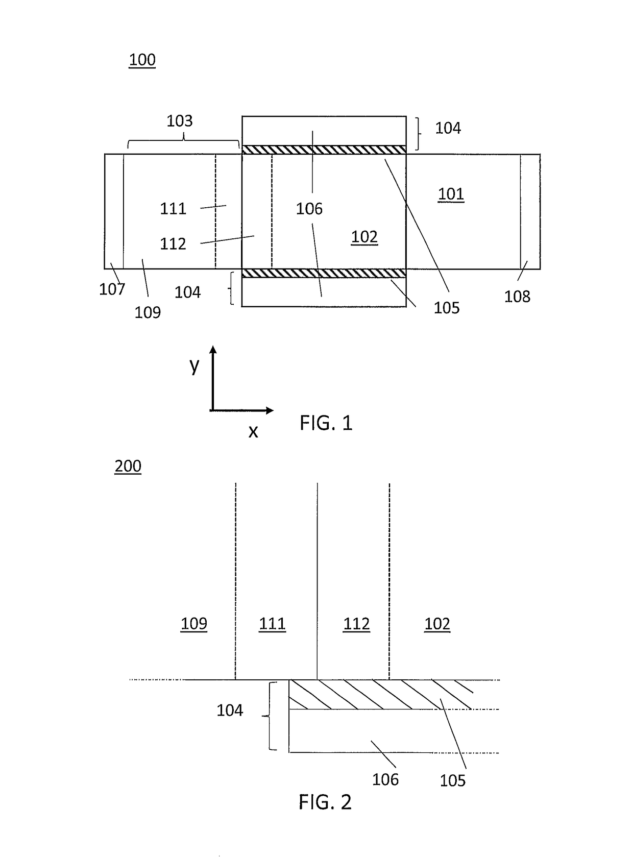
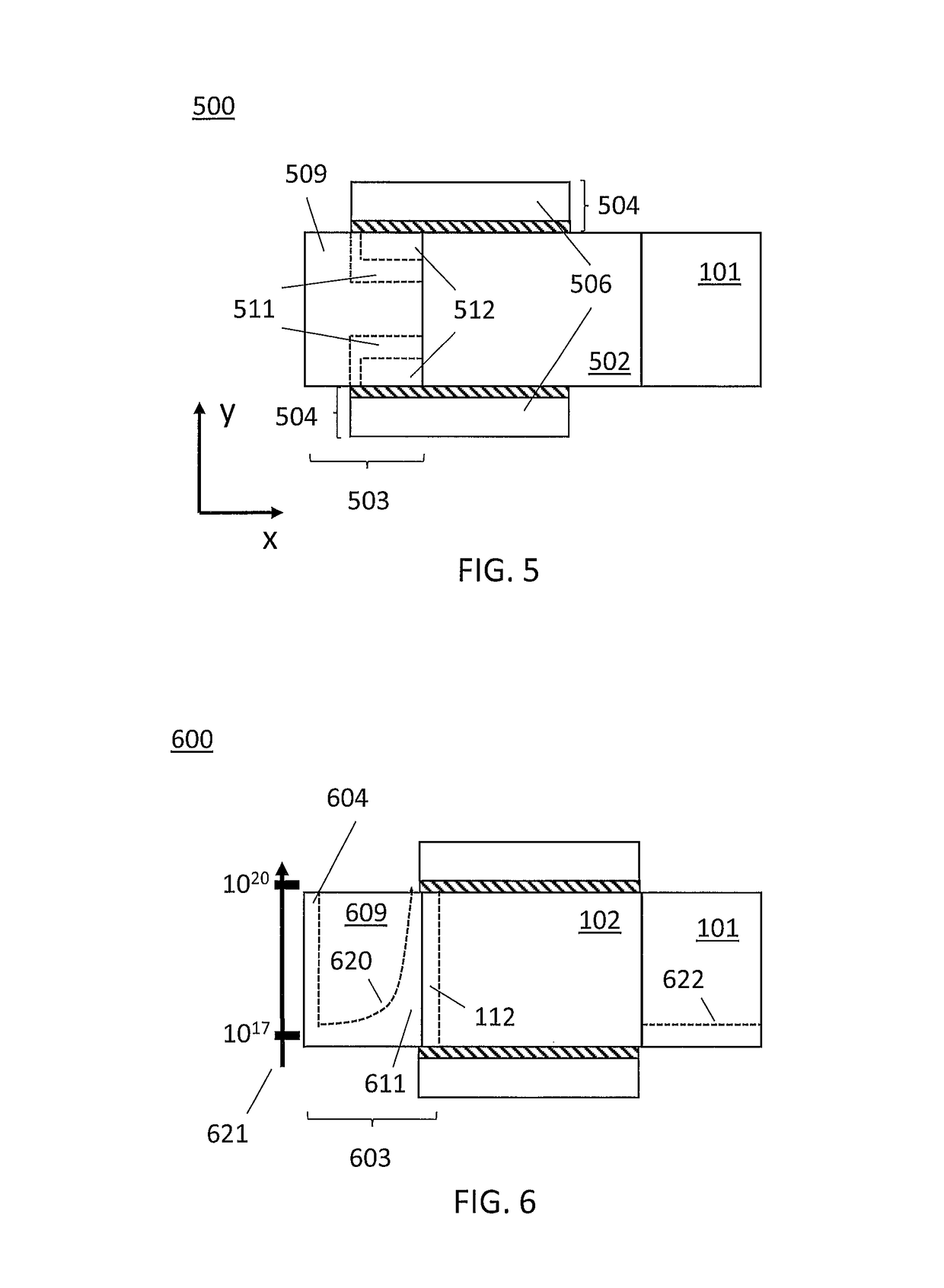
[0015]It is an advantage of embodiments that the source can have low doping levels, thus reducing doping degeneracy and reducing the energetic distance Ef-Ec, hence keeping subthreshold swing low. This is particularly advantageous for example for low power applications. It is an additional advantage that there is a large electrical field produced by the pocket formed by the highly doped section, improving tunneling and hence keeping a large on-current. The presence of the n-pocket allows to keep the electrical field high, while still in the remainder of the source the doping may be reduced.
[0028]A circuit according to embodiments may comprise an n-TFET and a p-TFET in complementary metal oxide semiconductor (CMOS) inverter configuration. It is an advantage of embodiments that such CMOS inverter configuration presents good complementarity.

Problems solved by technology

However, secondary effects of this miniaturization are noticeable.
While scaling of geometrical dimensions is being continued, scaling of operating voltage is saturating, with leakage currents and heating issues being difficult to solve.
This leads to an increase in short-channel effects, as the electric fields present in the devices become larger.
Power density increases as well, increasing the demands on cooling.
This also limits the lower voltage of operation, rendering the MOSFET as sub-optimal for some low-power applications.
The challenge in case of TFETs is how to obtain a steep SS and a high on-current (ION).
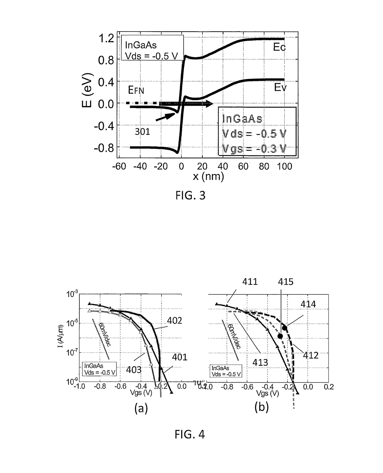
TFETs, both n-type and p-type, have been verified experimentally, both in Si and III-V materials, but the SS and on-currents which are obtained today are insufficient, and the current models do not allow for an optimization of both parameters simultaneously.
Despite the advances towards TFETs with high on-current and low subthreshold swing, integrated circuits for logic and memory applications comprising TFET are still sub-optimal because such transistors do not present good complementarity.
While TFETs with n-doped drains (n-TFETs) can reach a high on-current and good subthreshold swing, TFETs with p-doped drain (p-TFETs) present worse characteristics, even in the n-p-i-p configuration.
A problem arising from a high doping level is an increase of degeneration level, which makes the semiconductor of the source act as a conductor rather than as a semiconductor.
Among other problems, it has been shown that subthreshold swing is affected negatively by source degeneration.
The disadvantages of this technique are that the fabrication of these heterojunctions is complex, and the junction usually presents a relatively high density of stacking faults, dislocations and voids, due to the differences in material composition and, in some materials, also differences in crystal cell size for the different crystals structures.
These faults tend to increase the off-current of the device, introduce new trap states, and even may change the band alignment, possibly leading to an increase in tunneling distance.
Despite the possibility to use high DOS materials in the heterostructure, the DOS in the conduction band of typical III-V direct bandgap materials is still low, and degeneracy will occur at high doping regardless of defects and dislocation.

Method used


Image

  • Layered structure of a P-TFET
  • Layered structure of a P-TFET
  • Layered structure of a P-TFET

Examples


Embodiment Construction

[0040]The present invention will be described with respect to particular embodiments and with reference to certain drawings but the invention is not limited thereto but only by the claims. The drawings described are only schematic and are non-limiting. In the drawings, the size of some of the elements may be exaggerated and not drawn on scale for illustrative purposes. The dimensions and the relative dimensions do not correspond to actual reductions to practice of the invention.

[0041]The terms first, second and the like in the description and in the claims, are used for distinguishing between similar elements and not necessarily for describing a sequence, either temporally, spatially, in ranking or in any other manner. It is to be understood that the terms so used are interchangeable under appropriate circumstances and that the embodiments of the invention described herein are capable of operation in other sequences than described or illustrated herein.

[0042]Moreover, the terms top,...


PUM


Abstract

A p-type Tunnel Field-Effect Transistor comprises a drain p-type semiconductor region, a source n-type semiconductor region, and at least one gate stack. The source n-type semiconductor region comprises a lowly doped section with a length of at least 10 nm and with a doping level of n-type dopant elements below 5×10¹⁸ at / cm3 and, in contact with the lowly doped section, a highly doped section with a length between 1 monolayer and 20 nm and with a doping level of n-type dopant elements above 5×10¹⁸ at / cm3.

Description

INCORPORATION BY REFERENCE TO RELATED APPLICATIONS[0001]Any and all priority claims identified in the Application Data Sheet, or any correction thereto, are hereby incorporated by reference under 37 CFR 1.57. This application claims the benefit of European Patent Application No. EP 14188713.3, filed Oct. 13, 2014. The aforementioned application is incorporated by reference herein in its entirety, and is hereby expressly made a part of this specification.FIELD OF THE INVENTION[0002]A field effect transistor is provided, namely, a p-tunnel field-effect transistor and a circuit comprising such p-tunnel field-effect transistor.BACKGROUND OF THE INVENTION[0003]The metal-oxide-semiconductor field-effect transistor (MOSFET) technology, which forms the basic component of current integrated circuits, is reaching deep levels of miniaturization. The scaling occurs both for the geometrical dimensions as for the operating voltages, as this leads to better performance with a reduced footprint (re...

Claims


Application Information

Patent Timeline
Patent Type & Authority Patents(United States)
IPC IPC(8): H01L29/06H01L27/092H01L29/423H01L29/08H01L29/66H01L29/739H01L29/36H01L29/78
CPCH01L29/0688H01L27/092H01L29/0847H01L29/0895H01L29/42356H01L29/66977H01L29/7391H01L29/78H01L29/365H01L29/0665
Inventor VERRECK, DEVINVERHULST, ANNE S.
Owner INTERUNIVERSITAIR MICRO ELECTRONICS CENT (IMEC VZW)
Learn More