Read sensor having an in-stack biasing structure and an AP coupled free layer structure for increased magnetic stability

a free layer and sensor technology, applied in the field of read sensors of magnetic heads, can solve the problems of unstable magnetic spin of the free layer, difficult to accurately control the current fabrication method, and produce magnetic noise in response, and achieve the effect of increasing the stability of the ap coupled free layer structur

Inactive Publication Date: 2008-01-29
HITACHI GLOBAL STORAGE TECH NETHERLANDS BV
View PDF20 Cites 18 Cited by
  • Summary
  • Abstract
  • Description
  • Claims
  • Application Information

AI Technical Summary

Benefits of technology

[0020]The net magnetic moment of the AP coupled free layer structure has an antiparallel edge magnetostatic coupling with the net magnetic moment of the in-stack biasing structure. At the same time, the first AP coupled free layer has an antiparallel exchange coupling with the second AP coupled free layer. By forming the second AP coupled free layer with a thickness greater than a thickness of the first AP coupled free layer, the AP coupled free layer structure has a net magnetic moment in the direction of the second AP coupled free layer moment. The non-magnetic spacer layer is chosen so that first AP coupled free layer has a parallel interlayer (Neel or Orange-peel or positive exchange) coupling with the in-stack biasing structure, so that the interlayer coupling adds to the edge magnetostatic coupling to thereby increase the stability of the AP coupled free layer structure.

Problems solved by technology

Typically, magnetic spins of the free layer are unstable in small sensor geometries and produce magnetic noise in response to magnetic fields.
The efficacy of the method of stabilization depends critically on the precise details of the tail stabilization, which is difficult to accurately control using present fabrication methods.
Unfortunately, Neel coupling favors a parallel orientation between the magnetization of the layers and therefore undermines the effectiveness of the in-stack biasing structure.
However, with current high density storage requirements, it is difficult to achieve a low thickness for the free layer without rendering it inoperative.

Method used


Image

  • Read sensor having an in-stack biasing structure and an AP coupled free layer structure for increased magnetic stability
  • Read sensor having an in-stack biasing structure and an AP coupled free layer structure for increased magnetic stability
  • Read sensor having an in-stack biasing structure and an AP coupled free layer structure for increased magnetic stability

Examples


Embodiment Construction

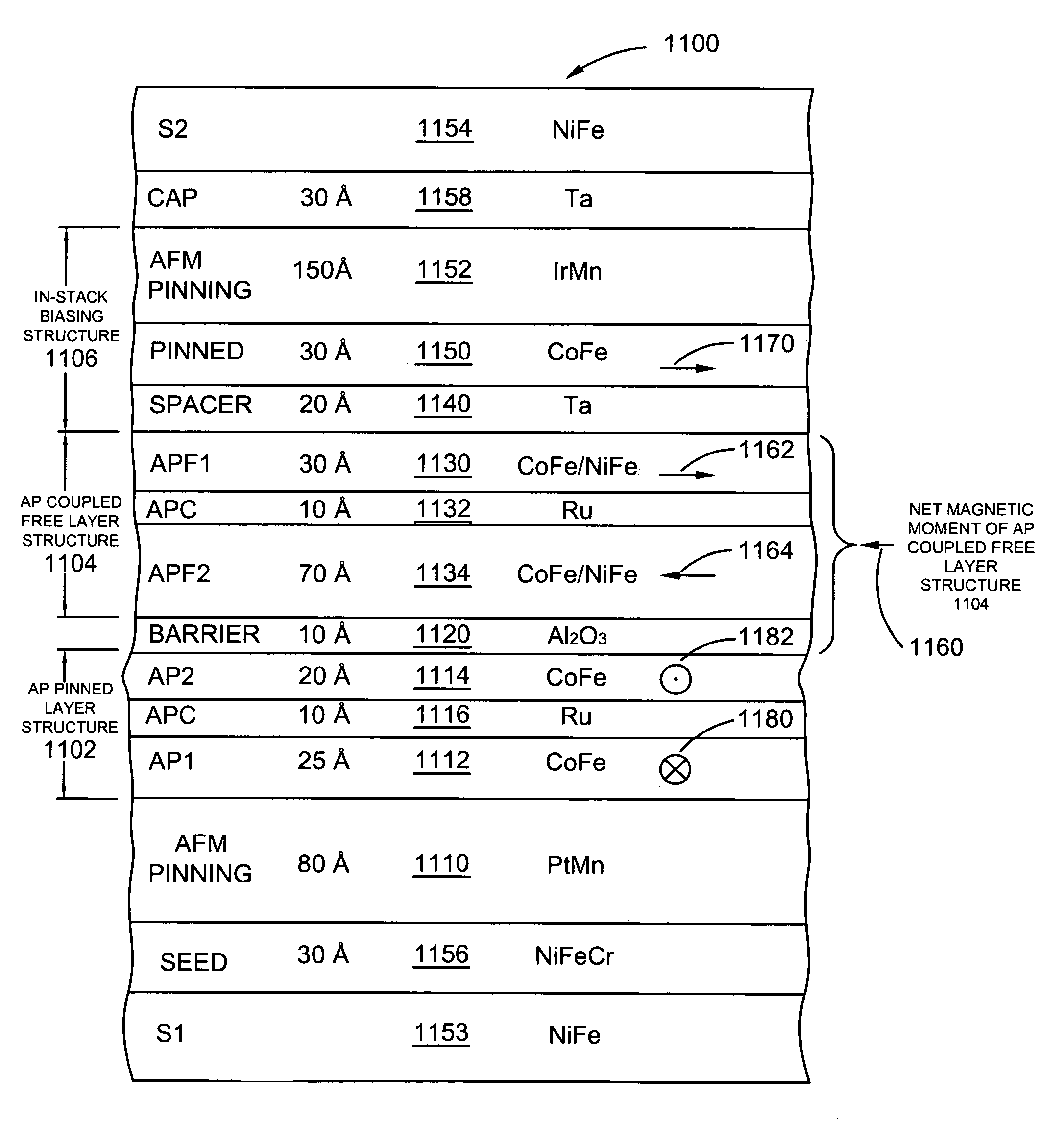
[0033]A magnetic head includes first and second shield layers and a read sensor formed between and in electrical contact with the first and second shield layers, where the read sensor is of the current-perpendicular-to-the-plane (CPP), current-in-to-the-plane (CIP) or tunnel valve type sensor. The read sensor includes an antiparallel (AP) coupled free layer structure, an in-stack biasing structure which stabilizes the AP coupled free layer structure and a nonmagnetic spacer layer formed between the in-stack biasing layer and the AP coupled free layer structure. The AP coupled free layer structure comprises a first AP coupled free layer adjacent to the nonmagnetic spacer layer, a second AP coupled free layer and an antiparallel coupling (APC) layer formed between the first and the second AP coupled free layers. The net moment of the AP coupled free layer structure has an antiparallel edge magnetostatic coupling with the in-stack biasing structure. At the same time the first AP couple...


PUM

PropertyMeasurementUnit
magneticaaaaaaaaaa
thicknessaaaaaaaaaa
net magnetic momentaaaaaaaaaa

Abstract

Current-perpendicular-to-the-plane (CPP), current-in-to-the-plane (CIP), and tunnel valve type sensors are provided having an antiparallel (AP) coupled free layer structure, an in-stack biasing structure which stabilizes the AP coupled free layer structure and a nonmagnetic spacer layer formed between the in-stack biasing layer and the AP coupled free layer structure. The AP coupled free layer structure has a first AP coupled free layer adjacent to the nonmagnetic spacer layer, a second AP coupled free layer, and an antiparallel coupling (APC) layer formed between the first and the second AP coupled free layers. The net moment of the AP coupled free layer structure has an antiparallel edge magnetostatic coupling with the in-stack biasing structure. At the same time, the first AP coupled free layer has an antiparallel exchange coupling with the second AP coupled free layer. By forming the second AP coupled free layer with a thickness greater than a thickness of the first AP coupled free layer, the AP coupled free layer structure has a net magnetic moment in the direction of the second AP coupled free layer moment. The non-magnetic spacer layer is chosen so that first AP coupled free layer has a parallel interlayer (Neel or Orange-peel or positive exchange) coupling with the in-stack biasing structure, so that the interlayer coupling adds to the edge magnetostatic coupling to increase a stability of the AP coupled free layer structure.

Description

BACKGROUND[0001]1. Field of the Technology[0002]The present application relates generally to read sensors of magnetic heads in data storage devices, and more particularly to current-perpendicular-to-the-plane (CPP), current-in-to-the-plane (CIP) or tunnel valve type sensors, which have an AP coupled free layer structure, an in-stack biasing structure which stabilizes the AP coupled free layer structure, and a nonmagnetic spacer layer formed between the in-stack biasing structure and the AP coupled free layer structure.[0003]2. Description of the Related Art[0004]Computers often include auxiliary memory storage devices having media on which data can be written and from which data can be read for later use. A direct access storage device (disk drive) incorporating rotating magnetic disks are commonly used for storing data in magnetic form on the disk surfaces. Data is recorded on concentric, radially spaced tracks on the disk surfaces. Magnetic heads which include read sensors are the...

Claims


Application Information

Patent Timeline
Patent Type & Authority Patents(United States)
IPC IPC(8): G11B5/127
CPCB82Y10/00B82Y25/00G11B5/313G11B5/3903G11B5/3909G11B5/3932
Inventor CHILDRESS, JEFFREY ROBINSONFONTANA, JR., ROBERT E.HO, KUOK SANTSANG, CHING HWA
Owner HITACHI GLOBAL STORAGE TECH NETHERLANDS BV
Why Eureka
Try Eureka