Network slot synchronization scheme for a computer network communication channel

a network communication channel and network slot technology, applied in data switching networks, store-and-forward switching systems, instruments, etc., can solve problems such as degraded signals on such links, expensive installation of wired links, and suffer from analog wireless communication links

Inactive Publication Date: 2008-01-29
CIRRUS LOGIC INC
View PDF69 Cites 11 Cited by
  • Summary
  • Abstract
  • Description
  • Claims
  • Application Information

AI Technical Summary

Benefits of technology

[0021]The first device may also maintain a clear channel assessment indicator that takes into account the first device's designated transmission time slot within the communication channel with respect to those of other network devices. Thus, the first device may transmit within the common communication channel upon an indication from the clear channel assessment indicator that the channel is available for transmission, regardless of whether or not the transmission time timer indicates that the first device's designated transmission time has arrived. Usually, the clear channel assessment indication is made upon the

Problems solved by technology

Such wired links are expensive to install, especially where they are added after the original construction of the home.
Although easier to install than conventional wired communication links, analog wireless communication links suffer from a number of disadvantages.
For example, degraded signals may be e

Method used


Image

  • Network slot synchronization scheme for a computer network communication channel
  • Network slot synchronization scheme for a computer network communication channel
  • Network slot synchronization scheme for a computer network communication channel

Examples


Embodiment Construction

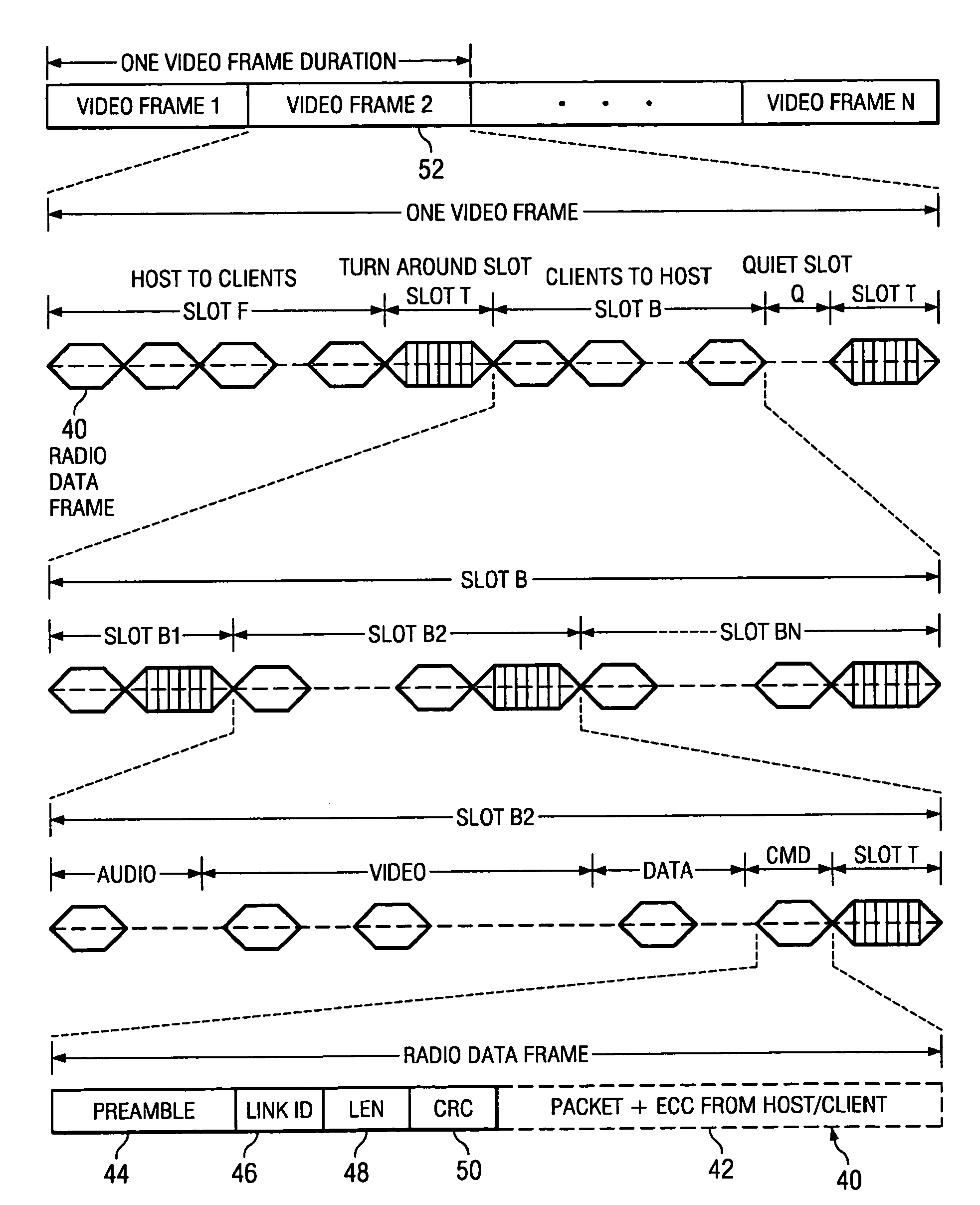
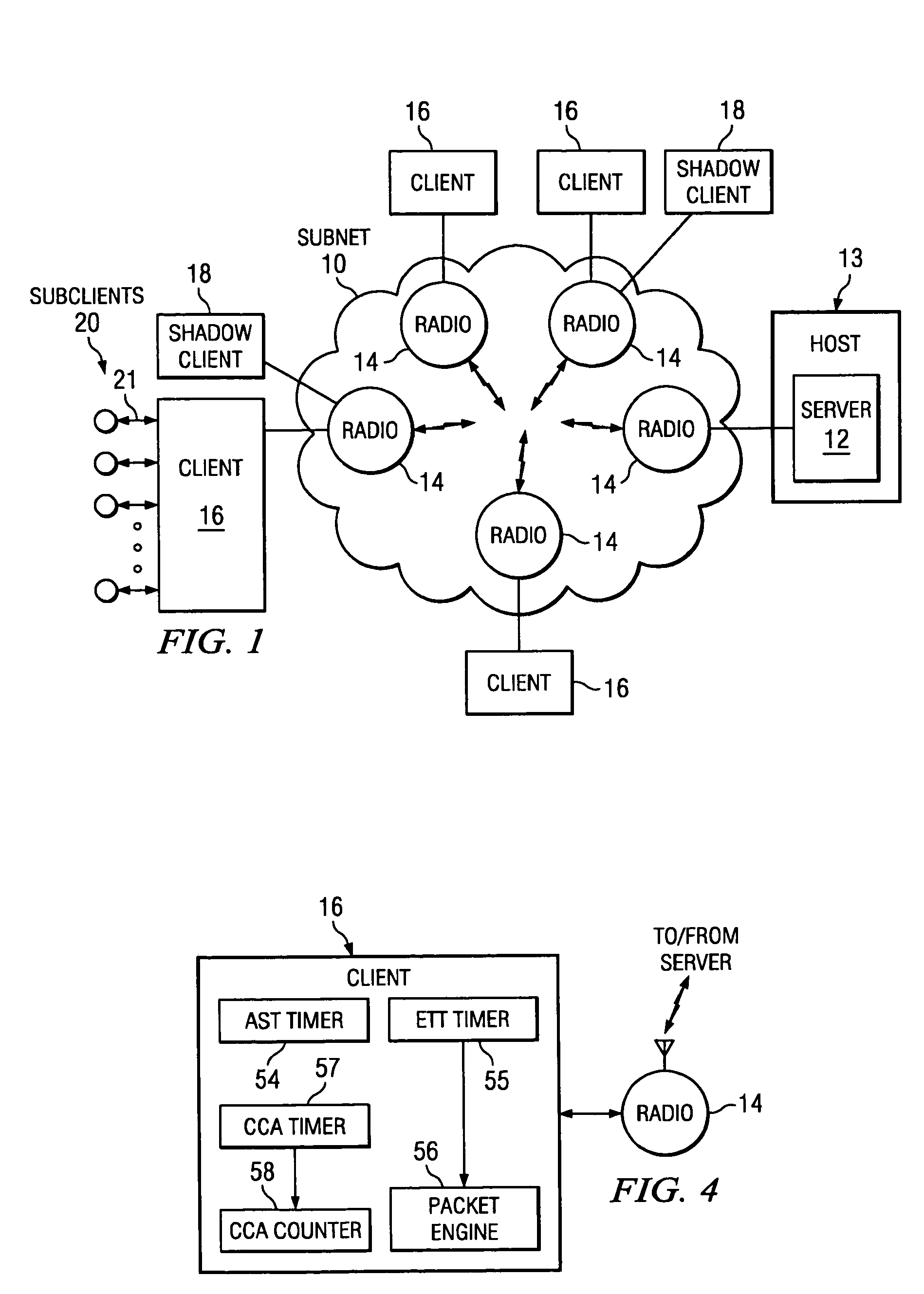
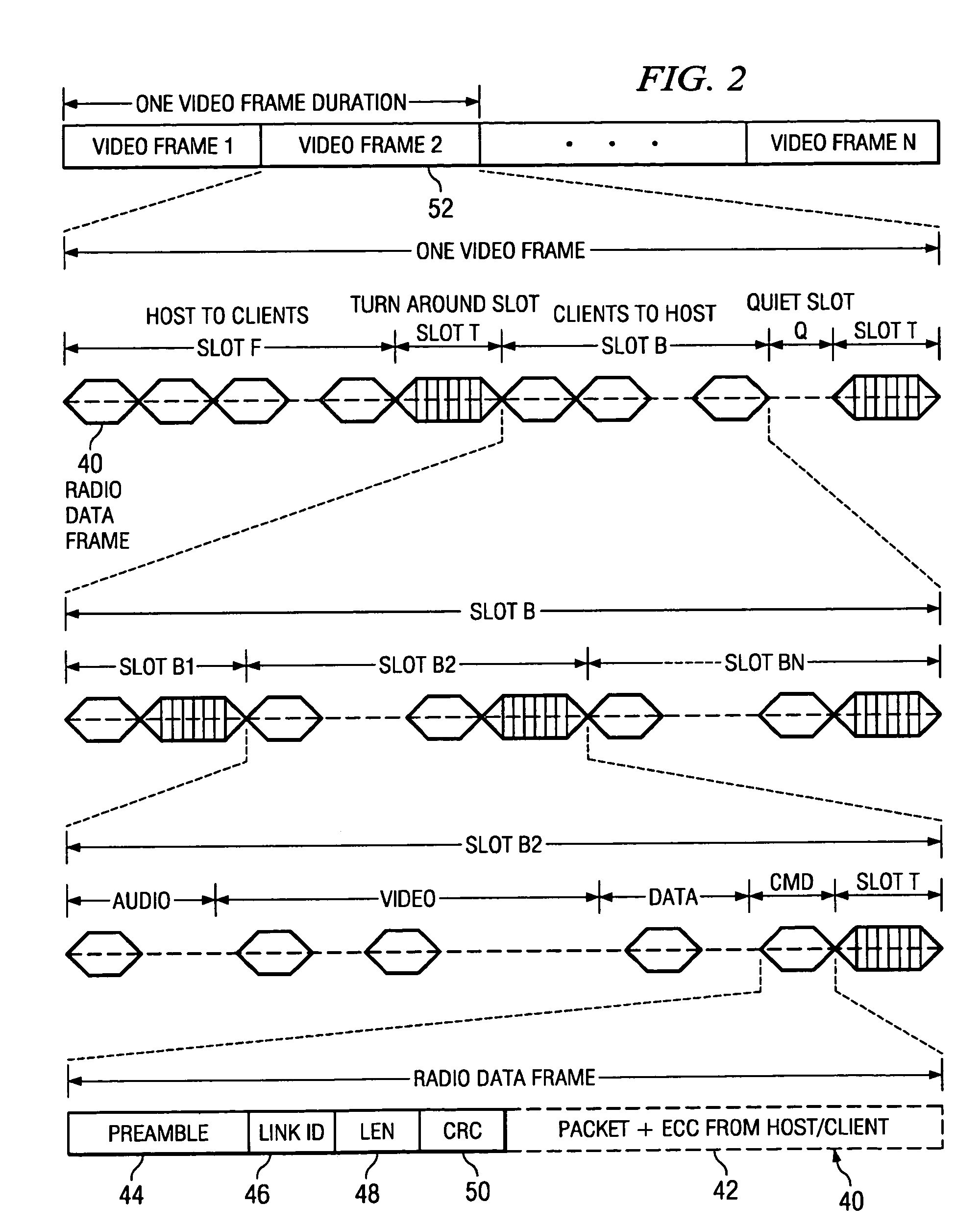
[0033]Described herein is a network slot synchronization scheme for use between a network master device (e.g., a server) and associated network clients within a communication channel of a computer network. The present scheme is generally applicable to a variety of network environments, but finds especially useful application in a wireless computer network which is located in a home environment. Thus, the present scheme will be discussed with reference to the particular aspects of a home environment. However, this discussion should in no way be seen to limit the applicability or use of the present invention in and to other network environments and the broader spirit and scope of the present invention is recited in the claims which follow this discussion.

[0034]One important term used throughout the following discussion is “channel”. As indicated above, a channel is defined as the combination of a transmission frequency (more properly a transmission frequency band) and a pseudo-random ...


PUM


Abstract

Synchronization within a common communication channel having designated transmission time slots for various devices of a computer network is maintained by allowing transmissions within the channel outside of a network device's designated time slot when a clear channel assessment indicates that a previous time slot is not being utilized by its associated device and/or upon receipt of an indication of the end of a transmission of another device in the network. The clear channel assessment preferably takes into account the device's designated transmission time slot within the communication channel with respect to those of other network devices and may be a time period that is the product of a predetermined clear channel waiting time and a numerical representation of the device's designated transmission time slot within the communication channel with respect to those of other network devices. The clear channel waiting time itself may be specified by a network master device as part of a network connection process. The network device may be configured to construct one or more packets for transmission within the network in advance of its designated time slot to accommodate these early transmissions.

Description

RELATED APPLICATION[0001]This application is a continuation-in-part of application Ser. No. 09 / 151,579, has now been abandoned, entitled “Method and Apparatus for Accessing a Computer Network Communication Channel”, filed Sep. 11, 1998, by Rajugopal R. Gubbi, Natarajan Ekambaram and Nirmalendu Bikash Patra, and assigned to the Assignee of the present application.FIELD OF THE INVENTION[0002]The present invention relates generally to a scheme for communications within a computer network and, in particular, to synchronizing such communications as occur between a central server and a number of client units across a wireless communications link.BACKGROUND[0003]Modern computer networks allow for inter-communication between a number of nodes such as personal computers, workstations, peripheral units and the like. Network links transport information between these nodes, which may sometimes be separated by large distances. However, to date most computer networks have relied on wired links to...

Claims


Application Information

Patent Timeline
IPC IPC(8): H04J3/16H04B7/24H04L1/16H04L12/28H04L12/413H04L12/56H04L29/06
CPCH04L1/16H04L29/06H04W72/0406H04L12/2803H04W12/10H04W28/20H04L69/24H04L63/126H04L9/40H04W72/20H04L12/56H04L12/413H04J3/16H04L12/28
Inventor GUBBI, RAJUGOPALSEVASTIAN, DONIAEKAMBARAM, NATARAJANPATRA, NIRMALENDU BIKASH
Owner CIRRUS LOGIC INC
Why Eureka
Try Eureka