
Method and apparatus for performing OPC using model curvature

a curvature and model technology, applied in the field of structure modeling and prediction, can solve the problems of limited capability of rule-based opc, affecting the yield of silicon, and affecting the efficiency of opc, so as to improve the manufacturability of a structur

Inactive Publication Date: 2008-01-29
SIEMENS PROD LIFECYCLE MANAGEMENT SOFTWARE INC
View PDF14 Cites 53 Cited by
  • Summary
  • Abstract
  • Description
  • Claims
  • Application Information

AI Technical Summary

Benefits of technology

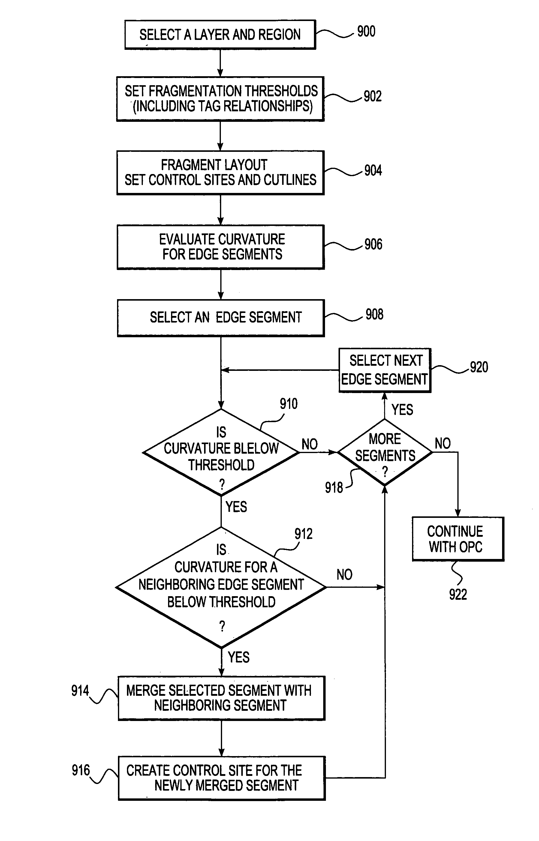
The present invention is a way to make a file that makes it easier to create things using photolithography. It starts by breaking down a structure into a series of vertices that make up a closed shape. The shape is then adjusted based on the estimated curvature of the light intensity or other parameter. This helps to make the structure easier to create using photolithography.

Problems solved by technology

However, with deep sub-micron processes, silicon yield is affected by several factors including reticle / mask pattern fidelity, optical proximity effects, and diffusion and loading effects during resist and etch processing.
Typical problems include line-width variations that depend on local pattern density and topology and line end pullback.
However, rule-based OPC has limited capability and when more complex OPC is desired, model-based OPC is used.

Method used


Image

  • Method and apparatus for performing OPC using model curvature
  • Method and apparatus for performing OPC using model curvature
  • Method and apparatus for performing OPC using model curvature

Examples


Embodiment Construction

[0024]Methods and apparatuses for structure prediction based on model curvature are described. In the following description, for purposes of explanation, numerous specific details are set forth in order to provide a thorough understanding of the invention. It will be apparent, however, to one skilled in the art that the invention can be practiced without these specific details. In other instances, structures and devices are shown in block diagram form in order to avoid obscuring the invention.

[0025]Reference in the specification to “one embodiment” or “an embodiment” means that a particular feature, structure, or characteristic described in connection with the embodiment is included in at least one embodiment of the invention. The appearances of the phrase “in one embodiment” in various places in the specification are not necessarily all referring to the same embodiment.

[0026]Some portions of the detailed descriptions which follow are presented in terms of algorithms and symbolic re...


PUM

PropertyMeasurementUnit
angleaaaaaaaaaa
perimeteraaaaaaaaaa
light intensityaaaaaaaaaa

Abstract

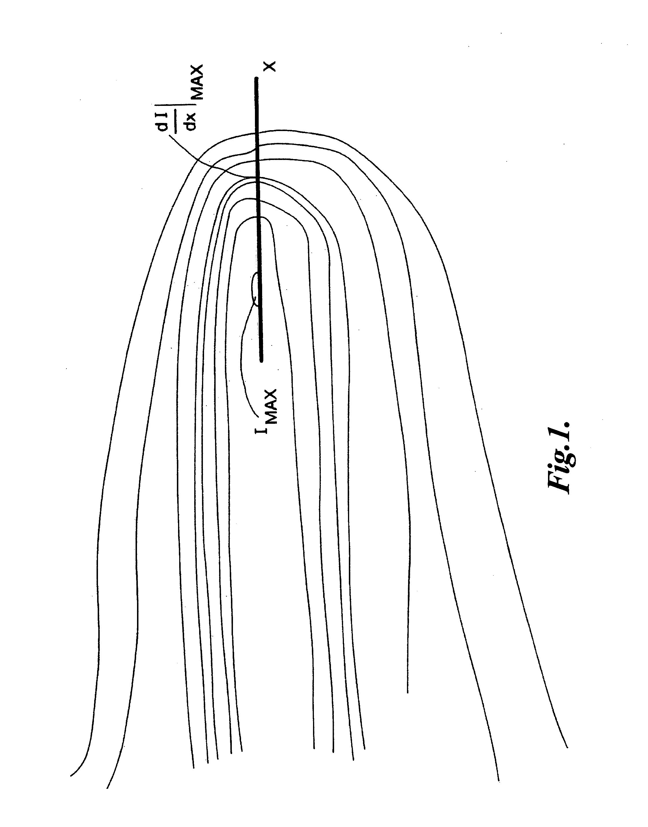
A method of preparing a file that stores layout of devices to be created with photolithography for optical and process correction (OPC). Polygons that define structures to be created are initially fragmented into edge segments and a simulation of how the edge segments will be printed under process conditions is performed. The results of the simulation are used to adjust / refragment the edge segments. In one embodiment, the curvature of light intensity at the edge segments is used to adjust the fragmentation of the polygons.

Description

CROSS-REFERENCE TO RELATED APPLICATION[0001]The present application is a continuation-in-part of U.S. patent application Ser. No. 09 / 457,410 (now U.S. Pat No. 6,643,616), filed Dec. 7, 1999, and issued Nov. 4, 2003, the benefit of which is claimed under 35 U.S.C. § 120.FIELD OF THE INVENTION[0002]The invention relates to structure modeling and prediction. More specifically, the invention relates to methods of enhancing the manufacturability of a physical structure, such as an integrated circuit, based on information derived from contour representations.BACKGROUND OF THE INVENTION[0003]As integrated circuits (ICs) become more dense, the widths of lines and components, as well as the separation between lines becomes increasingly smaller. Currently, deep sub-micron (<0.25 μm) processes are being used. However, with deep sub-micron processes, silicon yield is affected by several factors including reticle / mask pattern fidelity, optical proximity effects, and diffusion and loading effe...

Claims


Application Information

Patent Timeline
Patent Type & Authority Patents(United States)
IPC IPC(8): G06G7/62G03F1/00G06F17/50G03F1/36G03F7/20G06F1/14G06F7/60G06F17/00G06F17/10
CPCG03F1/144G03F1/36G03F7/70441
Inventor COBB, NICOLAS B.
Owner SIEMENS PROD LIFECYCLE MANAGEMENT SOFTWARE INC
Learn More