Hot gas deployment devices

a technology of deployment device and hot gas, which is applied in the direction of repellant gas/chemical self-defence device, ammunition projectile, weapon, etc., can solve the problems of imposing many risks on the law-enforcer, the use of “hot gas” canisters has inherent risks associated with the use of pyrotechnic devices, and the destruction of personal and real property

Inactive Publication Date: 2008-02-05
GIANDOMENICO THOMAS +1
View PDF10 Cites 21 Cited by
  • Summary
  • Abstract
  • Description
  • Claims
  • Application Information

AI Technical Summary

Benefits of technology

[0009]The present invention is directed to a HGDD which is light-weight, safe, efficient, and easy-to use in various law-enforcement situations.

Problems solved by technology

It is effective as a crowd control agent because it is an extremely severe skin and mucous membrane irritant and lacrimator, even at minute doses.
However, the use of “hot-gas” canisters has inherent risks associated with the use of pyrotechnic devices.
The flames and high temperatures produced by the pyrotechnic device may sometimes ignite combustible matter in its vicinity resulting in destruction of personal and real property.
Thus, even though law-enforcement agencies generally prefer to use “hot-gas” canisters, they are usually circumspect in the use of “hot-gas” canisters for law-enforcement activities.
However, the deployment of a full size “Burn-Safe” imposes many risks on the law-enforcement officer.
In such a situation, the officer may be exposed to hostile fire.

Method used


Image

  • Hot gas deployment devices
  • Hot gas deployment devices
  • Hot gas deployment devices

Examples


first embodiment

of the Invention

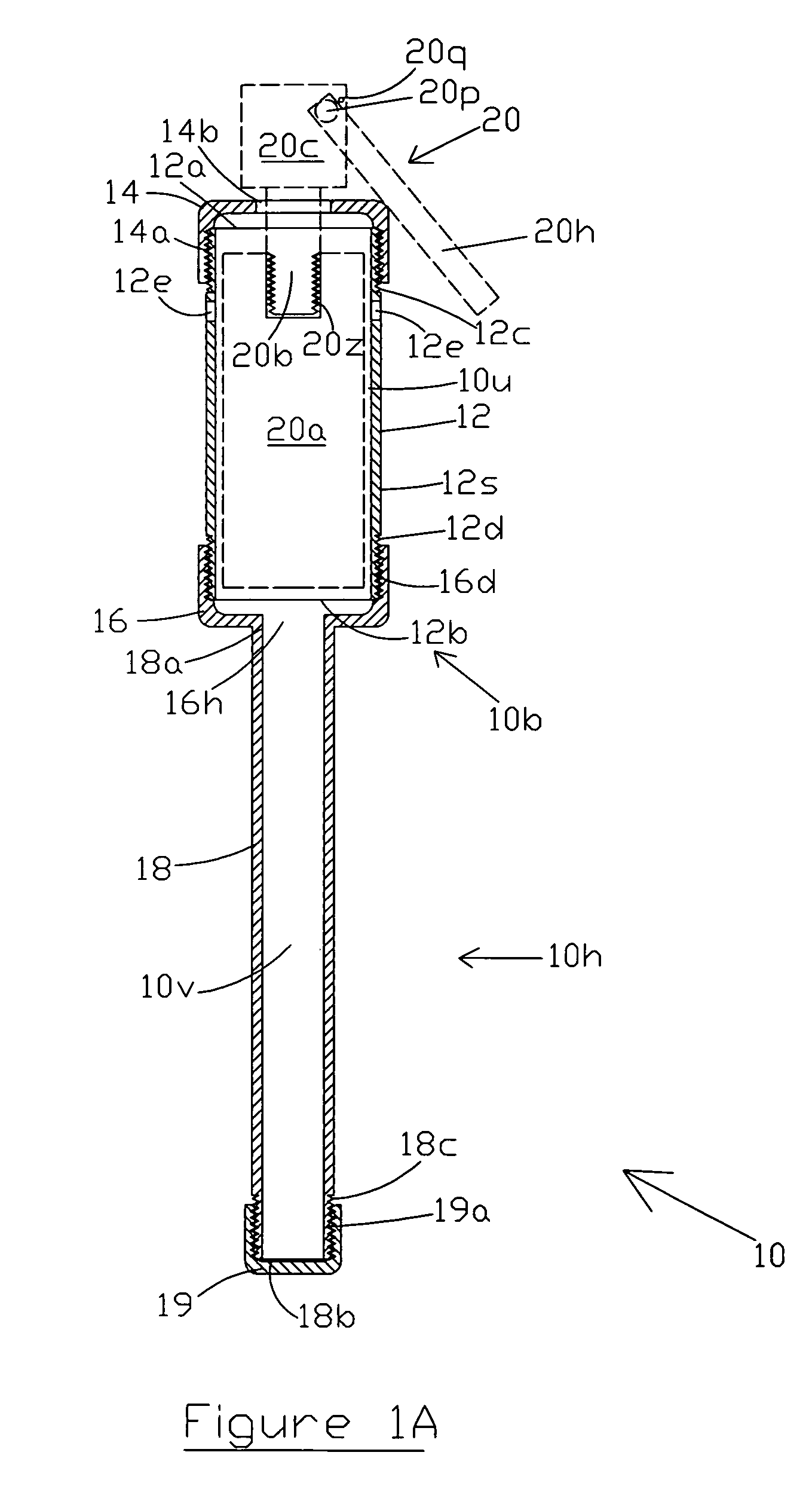
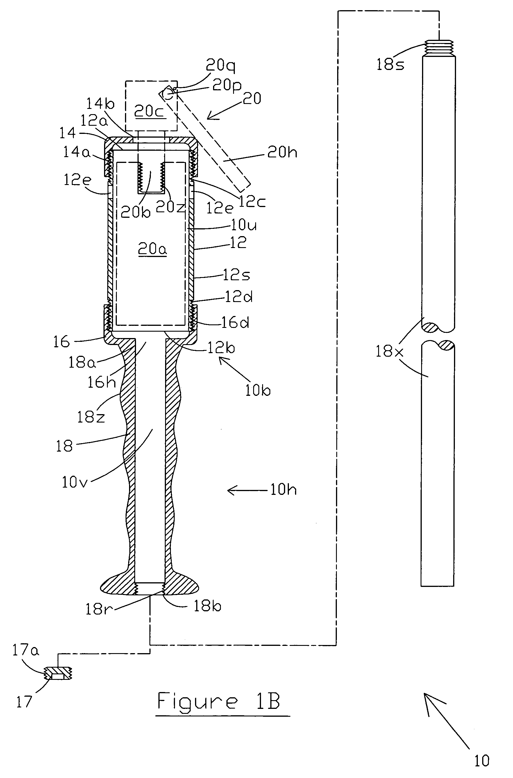
[0022]Referring to FIG. 1A, HGDD 10 has a club-shaped housing, comprising a bulbous section 10b and a stick handle section 10h. Bulbous section 10b comprises an internal cylindrical chamber for containing the tear-gas canister. The internal chamber is shown in FIG. 1A as tear-gas canister chamber (TGCC) 12. Physically, TGCC 12 is manufactured from a short piece of steel pipe 12s which has ends 12a and 12b. Pipe 12s is dimensionally designed to receive a 509 ACS tear-gas grenade canister, shown as 20a in FIG. 1A, in its inner cavity. Pipe 12s is provided with external screw threads 12c and 12d at each of its ends 12a and 12b respectively.

[0023]The housing of bulbous section 10b further includes a first pipe cap 14 which has internal threads 14a, that mate with threads 12c of pipe 12s. Pipe cap 14 is screwed over end 12a of pipe 12s. The housing of bulbous section 10b further includes a second pipe cap 16 which also has internal threads 16d, that mate with threads 12d ...

second embodiment

of the Invention

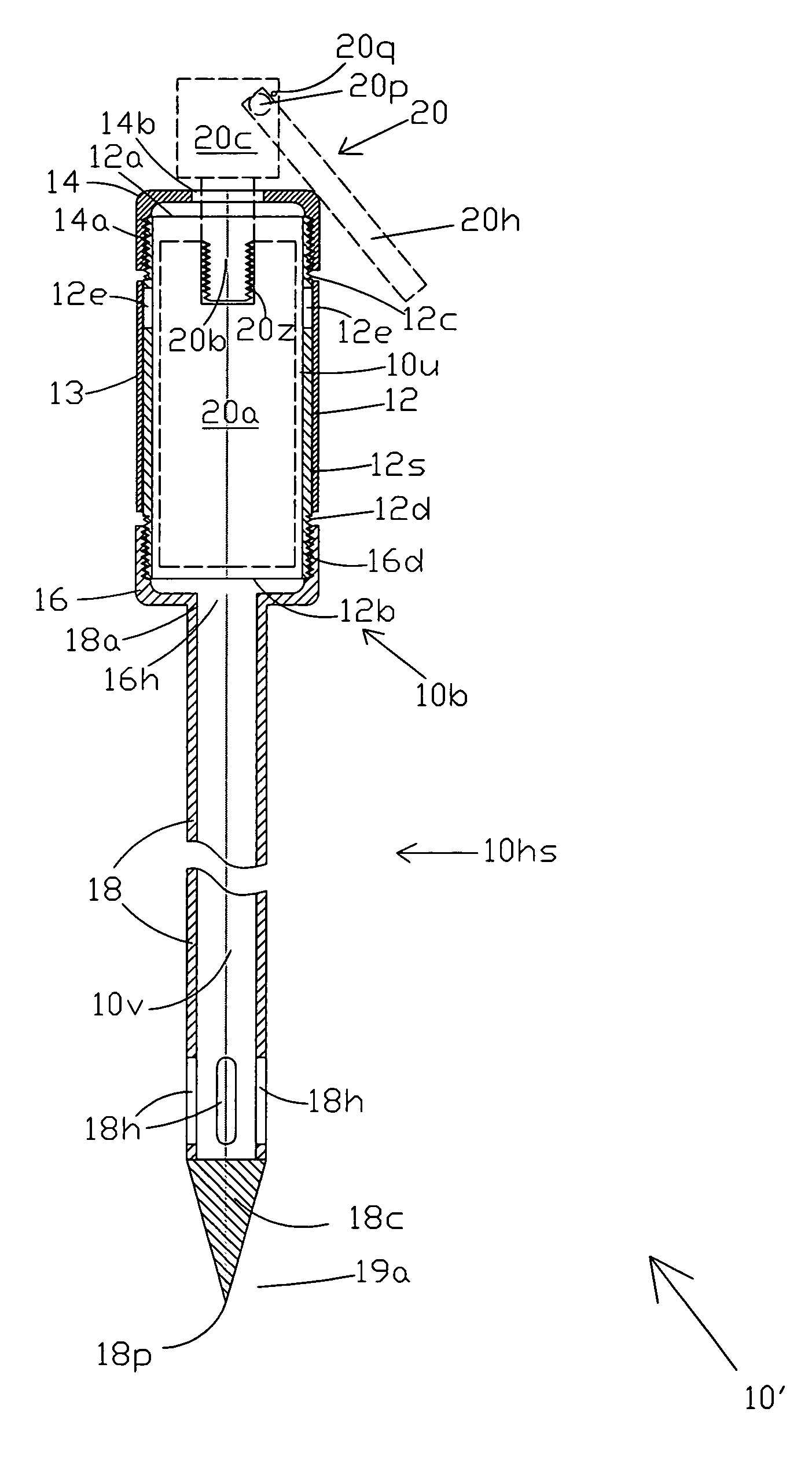
[0033]FIG. 2 shows a second embodiment of the HGDD of the present invention which is designed for penetrating through the building wall or ceiling or roof to release the tear-gas into the building space to flush out the barricaded law-resister therefrom.

[0034]As shown in FIG. 2, HGDD 10′ has a bulbous end 10b which is identical to the bulbous end 10b of HGDD 10 of FIG. 1. However, in this embodiment, during normal operation, the tear-gas is released through openings in tubular section 10hs rather than through bulbous section 10b, as will be described later. A cylindrical sleeve 13 of a pressure-distensible flexible material such as rubber or other such elastic material is fitted over TGCC 12 to cover tear-gas release openings 12e. The pressure-distensible flexible material used could be rubber or any other such elastic material which will be obvious to one skilled in the art. In practice, cylindrical sleeve 13 has been satisfactorily configured from a short piece of ...

third embodiment

of the Invention

[0040]FIG. 3A shows a third embodiment of the HGDD of the present invention which is designed for deploying larger tear-gas grenades such as the 555 ACS from Federal Laboratories Inc.

[0041]As shown in FIG. 3A, HGDD 100 has a housing 100b which has an internal cylindrical chamber, shown as TGCC 112. TGCC 112 is configured from a large-diameter steel pipe 112s which is dimensionally designed to receive the 555 ACS tear-gas grenade. Housing 100b also includes a cap-closure 114 which has internal threads 114a that engage mating external-threads 112c on the first end 112a of pipe 112s. Cap closure 114 is screwed onto first end 112a of pipe 112s. Further, cap closure 114 has a concentric hole 114b to allow for the insertion of threaded projection 120b of tear-gas grenade 120, as described previously with respect to HGDD 10 of FIG. 1A. A metal handle 114h, which is similar to a bucket-handle, is screwed or otherwise attached on to the dome of cap 114 to enable the user to t...


PUM


Abstract

A hot gas deployment device for safely deploying a “hot” tear-gas canister to flush out barricaded law-resisters. The device includes an internal chamber for inserting the tear-gas canister therein, securing means to secure the canister in place during deployment, and a handle for easy operation. The chamber safely contains the hot-gases produced by the tear-gas canister to reduce the risk of causing a fire in the barricaded space. Tear-gas release orifices on the chamber's housing release the tear-gas from the chamber. One embodiment of the device includes a hollow spear for releasing the tear-gas through walls and other obstructions. Another embodiment of the device is suitable for hurling with a tear-gas grenade launcher.

Description

CROSS-REFERENCE TO RELATED APPLICATION[0001]This application claims priority from U.S. Provisional Application No. 60 / 670,378 filed on Apr. 11, 2005.FIELD OF THE INVENTION[0002]This invention relates to devices, which can be used by law enforcement officers, for safely deploying “hot” tear-gas grenades.BACKGROUND OF THE INVENTION[0003]Tear-gas has long been used by law-enforcement agencies as a means for controlling unruly crowds and for flushing out barricaded law-resisters. Two types of tear-gas canisters are commonly in use: “cold-gas” and “hot-gas”, which differ in the mechanism used to disperse o-chlorobenzylidenemalononitrile (CS). CS is the active ingredient in tear-gas, which irritates the mucous membranes in the eyes, nose, mouth and lungs, and causes tearing, sneezing, coughing, etc. Physically, CS is a white crystalline substance, which is usually mixed with a pyrotechnic compound in a grenade or canister for use. When used, it is generally suspended in a smoke or a fog o...

Claims


Application Information

Patent Timeline
Patent Type & Authority Patents(United States)
IPC IPC(8): F42B12/46
CPCF41H9/10F42B12/46F42B27/08
Inventor GIANDOMENICO, THOMASGIANDOMENICO, THOMAS ANTHONY
Owner GIANDOMENICO THOMAS
Why Eureka
Try Eureka