
Hockey stick blade and a method of making thereof

a technology of hockey stick and blade, which is applied in the field of hockey stick blade, can solve the problems of reducing the mechanical properties of the blade as a whole, unable to provide an optimized combination of minimum weight and maximum stiffness/strength, and reducing so as to reduce the importance of foam surface area, improve blade performance, and reduce the effect of energy loss

Inactive Publication Date: 2008-02-05
SPORT MASKA
View PDF18 Cites 69 Cited by
  • Summary
  • Abstract
  • Description
  • Claims
  • Application Information

AI Technical Summary

Benefits of technology

The aligned fiber structure improves the blade's rigidity, minimizing deflection and maximizing energy restitution to the puck, providing enhanced performance and durability.

Problems solved by technology

Such methods yield blades having a weight essentially proportionate to the respective weight of the materials used, and usually fail to provide an optimized combination of minimum weight and maximum stiffness / strength.
For example, in the case of sandwich-type blades, a main weakness and a reduced service life are related to a non-satisfactory quality of the joining step or of the gluing step between a core and outer walls, thus resulting in a tendency to delaminate, peel or tear.
As soon as peeling initiates, for example, the mechanical properties of the blade as a whole are reduced, thereby jeopardizing the quality of the hockey stick itself.
Efforts to optimize a long-term strength of sandwich-type blades have involved using braids around the core of the sandwich structure, which results in an effective increase of strength and life limit of so-called high-performance blades.
The above efforts still fail as far as the weight problem is concerned.
It has been noted that assembling a light shaft and a relatively heavy blade results in an unbalanced hockey stick, which is unacceptable in the field of high-performance hockey.
The negative particularity of such molding technology is the fact that, when the pre-assembly of the foam insert around which the carbon fiber cloth or braid is positioned inside the cavity portion of the mold, there is no specific fiber strengthening or specific fiber alignment.
The dry fiber clothe or braid is relatively loose and it is in this state that it will be resin impregnated after mold closing and resin injection, thus generating wrinkles, for example, and non uniform adherence with the foam core.
Such situation results in a molded blade in which the continuous reinforcing fibers are not well aligned and relatively misoriented inside the solidified resin matrix.
Therefore, molding hockey stick blades according to the conventional close-mold technology does not generate an optimum stiffness, which is a main factor required to totally convert the induced energy by the player into puck speed.
The extra blade deflection, when subjected to load and due to carbon fiber molded state (unstraightened and misoriented), is a serious handicap to optimize puck speed in a slap shot, for example.

Method used


Image

  • Hockey stick blade and a method of making thereof
  • Hockey stick blade and a method of making thereof
  • Hockey stick blade and a method of making thereof

Examples


Embodiment Construction

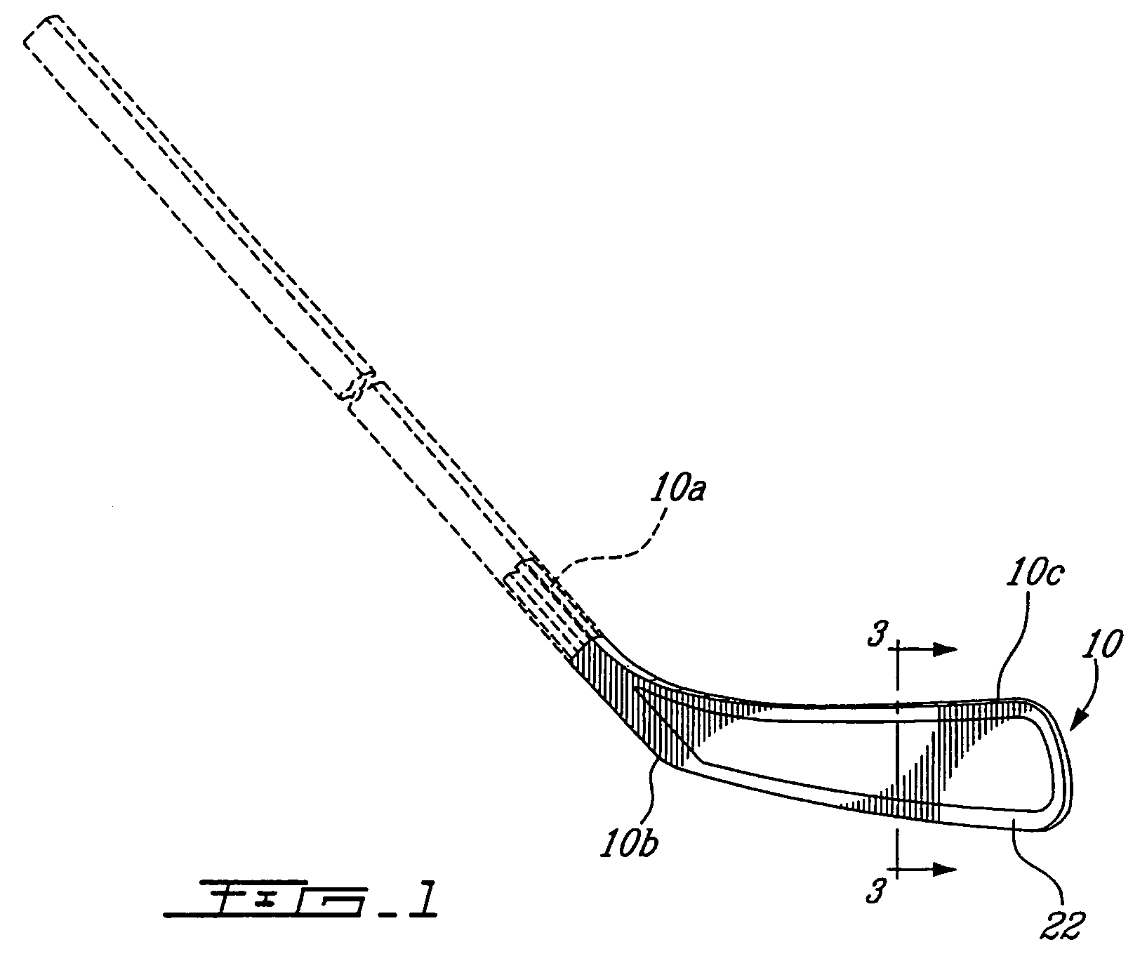
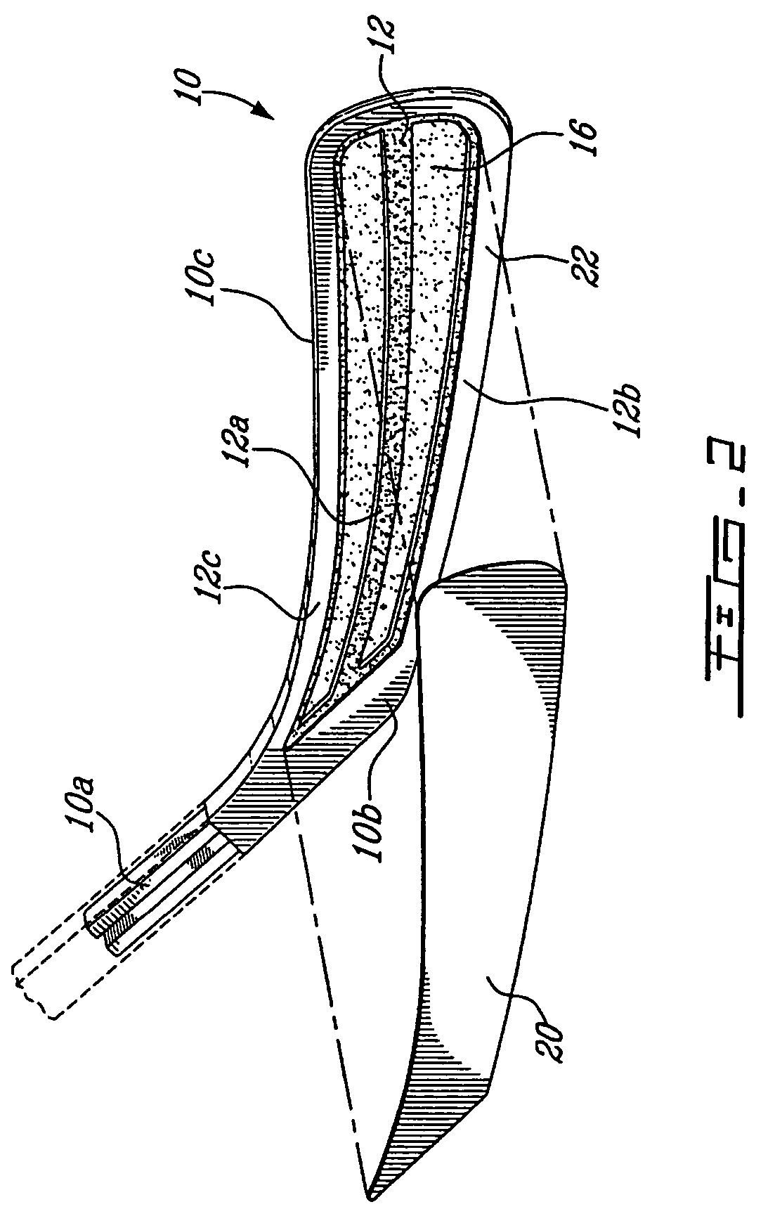
[0058]This present invention is concerned in providing a hockey stick blade 10 such as that illustrated in FIGS. 1 and 2 which is mounted to a hockey stick shaft 11. The blade 10 includes a shaft connecting portion 10a, a heel portion 10b and a puck contacting portion 10c.

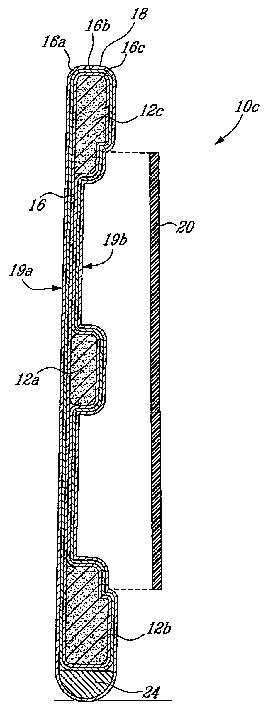
[0059]As illustrated also in FIG. 3, the puck contracting portion 10c comprises a core 12 formed of light weight material, such as low-density foam or carbon, and a tubular fiber braid jacket 16.

[0060]In the present embodiments, the core 12 is formed of three longitudinal spaced-apart sections 12a, 12b, 12c, onto which the fiber braid jacket 16 has been pulled or slid. Core section 12a is located at about the middle of the blade while core sections 12b and 12 are respectively located at the bottom and at the top of the blade. Each section may have a selected width. A combined height of these three sections may represent about half the height of the blade 10 as a whole. However, the number of core sections 12 may b...


PUM

PropertyMeasurementUnit
weightaaaaaaaaaa
perimeteraaaaaaaaaa
densityaaaaaaaaaa

Abstract

There is provided a hockey stick blade and a method of making thereof, wherein the blade is made in a composite material comprising a core formed of light weight material, such as foam, and a fiber braid jacket or tubular prepreg cloth, the core being partially hollow to define longitudinal cavities inside the blade assembly.

Description

FIELD OF THE INVENTION[0001]The present invention relates to hockey sticks. More specifically, the present invention is concerned with a hockey stick blade and a method of making such a blade.BACKGROUND OF THE INVENTION[0002]As is now well established in the art, the blade, as the hockey stick's striking surface, is a part submitted to extreme load conditions during shots like a slap shot, for example. The blade may be submitted to impact, torsion, bending, tension and shearing forces.[0003]Current methods of making hockey stick blades tend to meet requirements resulting from such a range of forces to which the blades are submitted, by resorting to different types of structures, including for example, monobloc structures, sandwich structures and reinforced structures. Such methods yield blades having a weight essentially proportionate to the respective weight of the materials used, and usually fail to provide an optimized combination of minimum weight and maximum stiffness / strength....

Claims


Application Information

Patent Timeline
Patent Type & Authority Patents(United States)
IPC IPC(8): A63B59/14A63B59/70
CPCA63B59/14B29C70/086B29C70/345B29C70/865B29K2105/0827B29L2031/52A63B2102/24A63B59/70
Inventor JEANGATIEN, DANIELLUSSIER, REMILADOUCEUR, CAROLBELANGER, GERMAIN
Owner SPORT MASKA
Learn More