

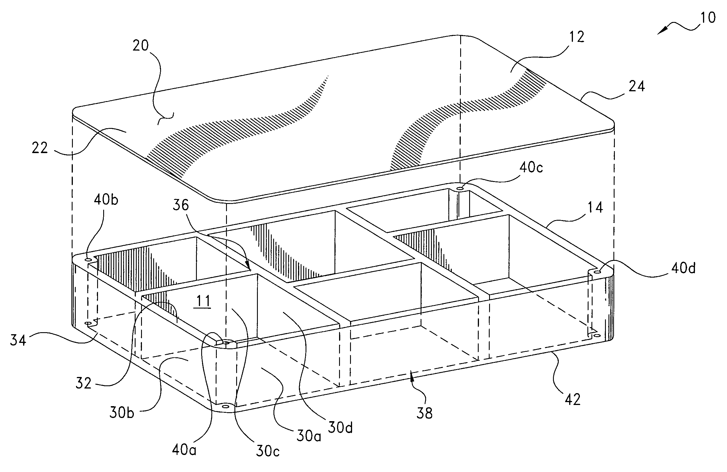
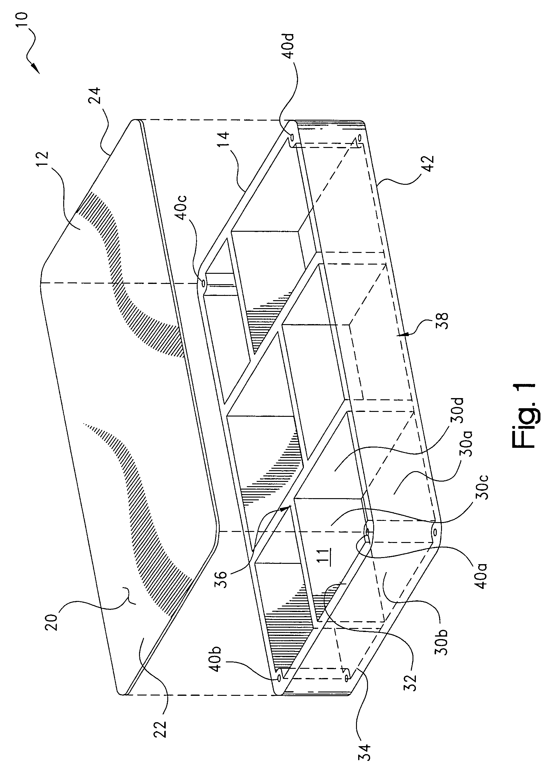
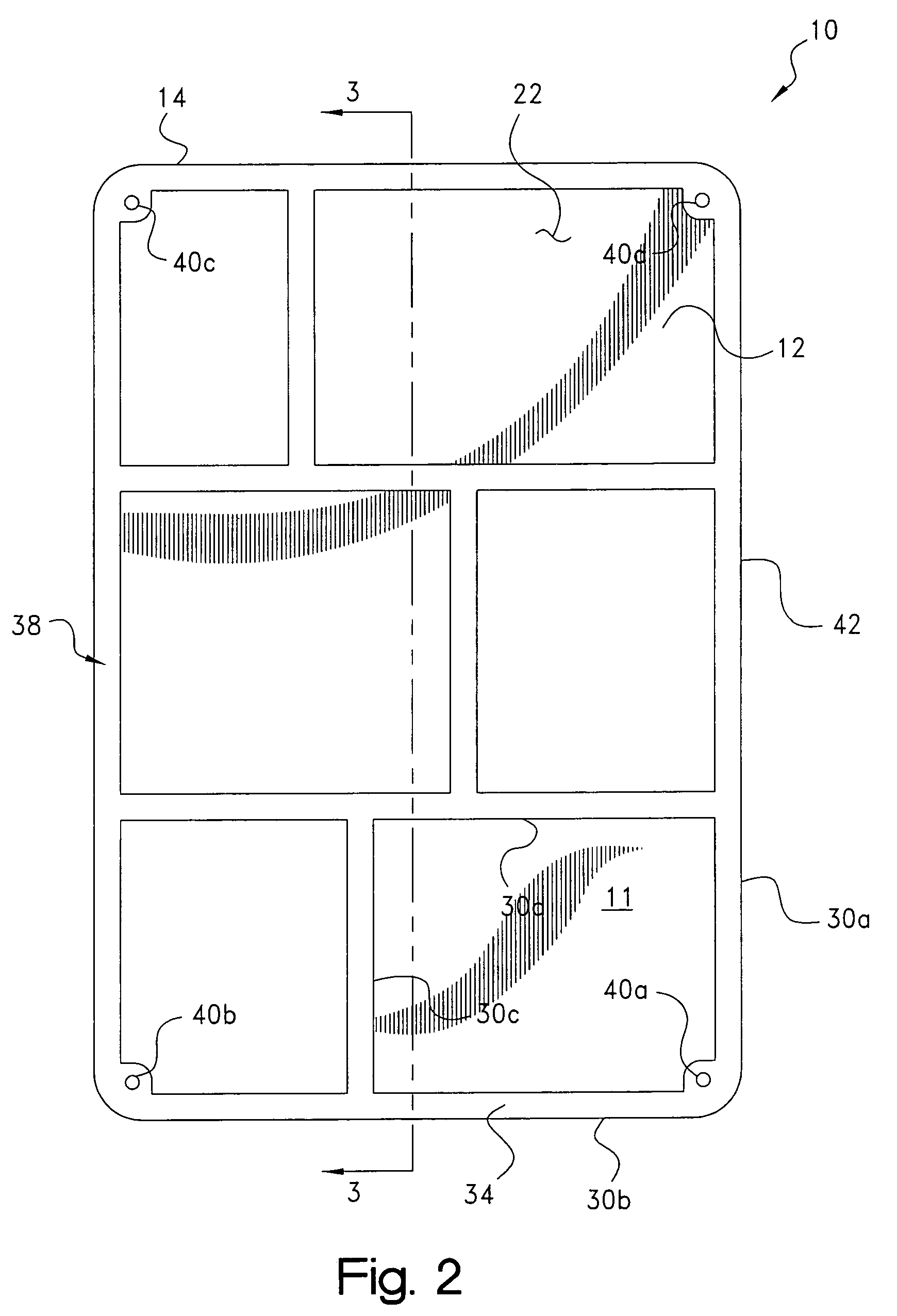
Combination metal and plastic EMI shield
a technology of electromagnetic interference and composite metals, applied in the field of electromagnetic interference shields, can solve the problems of inability to use shielding applications, difficult to fabricate in cost-effective manner into the complex shapes which may be required for certain applications, and relative cos
- Summary
- Abstract
- Description
- Claims
- Application Information
AI Technical Summary
Benefits of technology
Problems solved by technology
Method used
Image

Examples
Embodiment Construction
[0020]Certain terminology may be employed in the following description for convenience rather than for any limiting purpose. For example, the terms “forward” and “rearward,”“front” and “rear,”“right” and “left,”“upper” and “lower,”“top” and “bottom,” and “right” and “left” designate directions in the drawings to which reference is made, with the terms “inward,”“inner,”“interior,” or “inboard” and “outward,”“outer,”“exterior,” or “outboard” referring, respectively, to directions toward and away from the center of the referenced element, the terms “radial” or “vertical” and “axial” or “horizontal” referring, respectively, to directions or planes perpendicular and parallel to the longitudinal central axis of the referenced element. Terminology of similar import other than the words specifically mentioned above likewise is to be considered as being used for purposes of convenience rather than in any limiting sense.
[0021]In the figures, elements having an alphanumeric designation may be ...
PUM
 Abstract
Description
Claims
Application Information