Tactile feedback plunger switch

a plunger switch and tactile feedback technology, applied in the field of switches, can solve the problems of switch failure, contacting parts will begin to wear, switch failure eventually, etc., and achieve the effect of reducing resistance, increasing resistance to springs, and reducing resistance from the cover

Inactive Publication Date: 2008-02-05
INTERGRAPH HARDWARE TECH
View PDF32 Cites 23 Cited by
  • Summary
  • Abstract
  • Description
  • Claims
  • Application Information

AI Technical Summary

Benefits of technology

[0009]In certain embodiments the deformable section completely surrounds the plunger covering and the border completely surrounds the deformable section. When the plunger is in its initial biased position, the length of the deformable section is greater than the distance between the border and the plunger covering. Thus, in certain embodiments the deformable section is convex. As the plunger is pushed downward into the switch housing, the deformable section begins to fold and the resistance added by the covering decreases.

Problems solved by technology

The disadvantage of the toggle switch is that over repeated use the contacting parts will begin to wear, and the switch will eventually fail.
One problem with plunger type switches that operate in an on-off configuration is that they lack tactile feedback.
For example, the switch may change states when the plunger is pressed halfway and thus, pressing the plunger the additional halfway so that the plunger contacts the bottom of the housing, wastes the user's energy and may prematurely fatigue a user who must repeatedly push the plunger switch.

Method used


Image

  • Tactile feedback plunger switch
  • Tactile feedback plunger switch
  • Tactile feedback plunger switch

Examples


Embodiment Construction

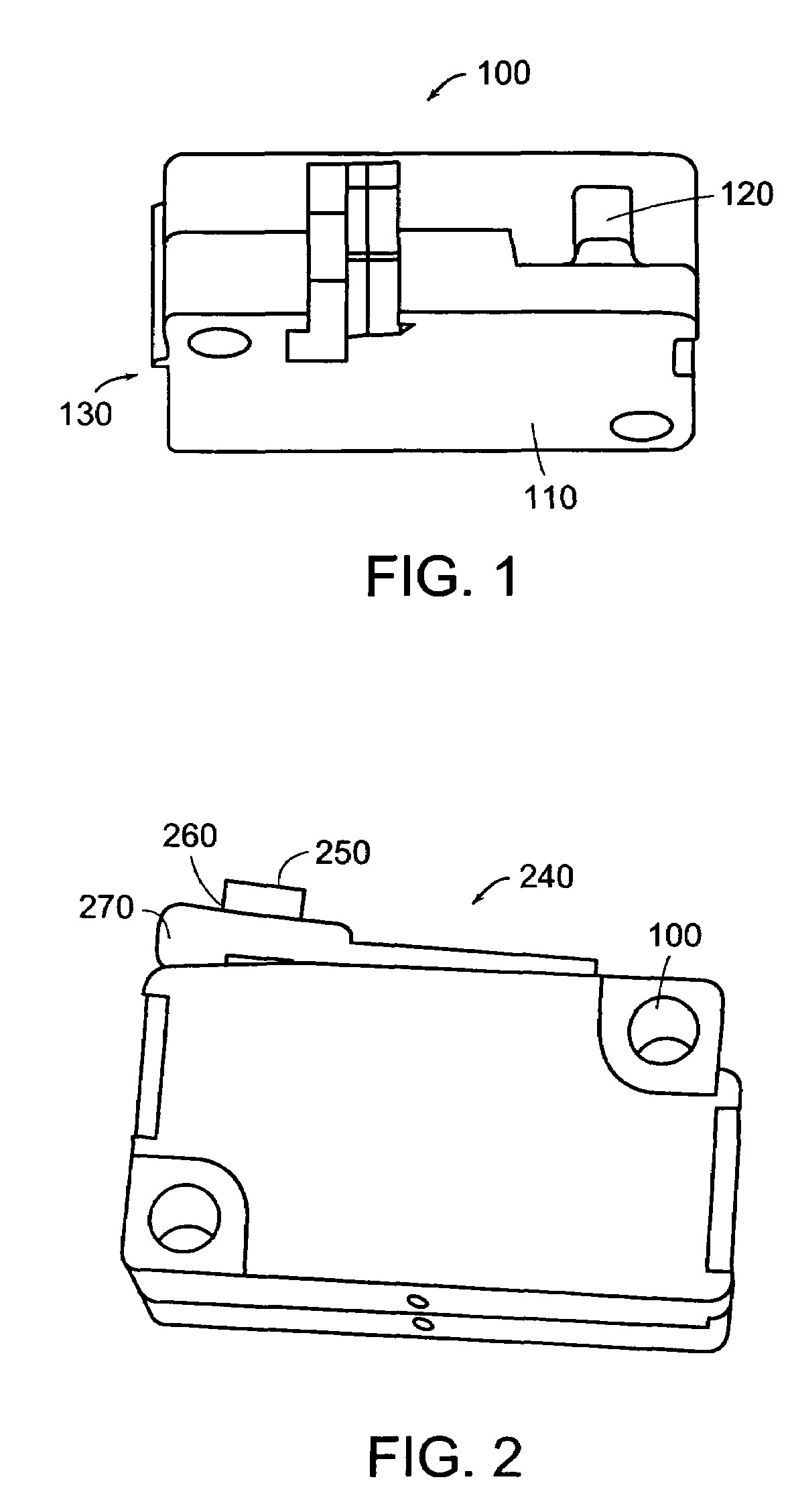
[0019]FIG. 1 is an image of a plunger switch 100. A plunger switch provides a non-mechanical switching mechanism, such that the state of the switch can be changed without mechanical parts having to come into physical contact to complete a circuit path. The plunger switch includes a body 110 that houses the plunger 120. Within the body of the plunger switch are electronics (not shown). The plunger switch 100 includes an output 130 for allowing a signal to be output indicating that the switch has changed states.

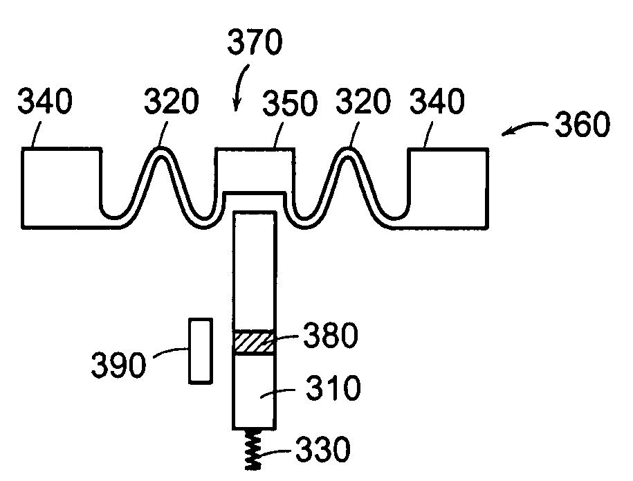
[0020]One type of plunger switch uses the Hall-Effect to change states. This type of switch includes a Hall-Effect sensor. When the plunger of the switch is depressed into the switch body, a magnetic portion of the plunger creates a magnetic field with the Hall-Effect sensor and a voltage drop typically across a thin layer of silicon. This voltage signal is amplified by internal circuitry and provided to the output 130 of the switch, and the voltage signal is an indicator of a ...


PUM


Abstract

A tactile feedback switching mechanism having a plurality of switching states. The tactile feedback switching mechanism includes a plunger switch having a plunger. When the plunger is displaced a given distance the switch changes state. A covering lies at least over the plunger switch and includes a border section and a deformation section. The covering may be formed from an elastic material such as an elastomer. When a user depresses the plunger, confirmation of a change in the state of the switch can be tacitly sensed by a change in resistance provided by the covering. The resistance of the covering changes by deformation of the deformation portion of the covering while the plunger is depressed.

Description

TECHNICAL FIELD AND BACKGROUND ART [0001]The present invention relates to switches and more specifically to plunger switches.[0002]It is known in the prior art to use a toggle switch for user input devices, such as in a keyboard. Toggle switches include two parts: a top that is moveable and a bottom that is stationary. The bottom contains a circuit path that includes a break in the circuit path. The top part of the toggle switch contains a conductive element on its bottom surface, which when depressed, comes into contact with the bottom part and completes the circuit allowing a signal to pass through the circuit. Thus, the circuit path may be closed by toggling the switch. Toggle switches require mechanical contact in order to close the circuit. The disadvantage of the toggle switch is that over repeated use the contacting parts will begin to wear, and the switch will eventually fail.[0003]It is also known in the art to use plunger type switches for switching operations. Plunger swi...

Claims


Application Information

Patent Timeline
Patent Type & Authority Patents(United States)
IPC IPC(8): H01H13/00
CPCH01H36/0006H03K17/97H01H2215/006H03K2217/96062
Inventor FLYNN, BRIANELLISON, KYLEGRIGORIAN, ERIC
Owner INTERGRAPH HARDWARE TECH
Why Eureka
Try Eureka