
Display and method for driving the same

a technology of display and drive, applied in the field of display, can solve the problems of reduced power consumption, large power consumption, and difficulty in applying the dot matrix inversion control to a display having a large screen, and achieve the effects of improving display quality, improving display quality, and improving display quality

Inactive Publication Date: 2008-02-05
COLLABO INNOVATIONS INC
View PDF5 Cites 19 Cited by
  • Summary
  • Abstract
  • Description
  • Claims
  • Application Information

AI Technical Summary

Benefits of technology

"The present invention provides a display that can achieve both image quality and power consumption reduction. The invention includes a display panel with scanning lines and signal lines, a source driver for driving the sub-pixels, and a controller for supplying a control signal to the source driver. The source driver has a polarity switching circuit for switching the polarity of the output voltage, and the timing of switching is shifted for each frame. The invention also includes a method for driving the display by supplying an output voltage with switched polarity for each n horizontal scanning periods. The invention can improve display quality while reducing power consumption."

Problems solved by technology

In the above-described dot matrix inversion control shown in FIG. 7A, however, power consumption is large, and thus it has been difficult to apply this dot matrix inversion control to a display having a large screen.
Also, in the two line dot matrix inversion control shown in FIG. 7B in which recovery of electrical charge is not carried out, power consumption is reduced; however, display quality is undesirably degraded.
To the contrary, in the two line dot matrix inversion control shown in FIG. 7C in which recovery of electrical charge is carried out in each horizontal scanning period, display quality is improved; however, a loss in electric power occurs during recovery of electrical charge as described above, and therefore, power consumption cannot be sufficiently reduced.
However, according to this method, although image quality can be improved, it is difficult to reduce power consumption.

Method used


Image

  • Display and method for driving the same
  • Display and method for driving the same
  • Display and method for driving the same

Examples


Embodiment Construction

[0049]Hereinafter, a liquid crystal display according to an embodiment of the present invention will be described with reference to the accompanying drawings.

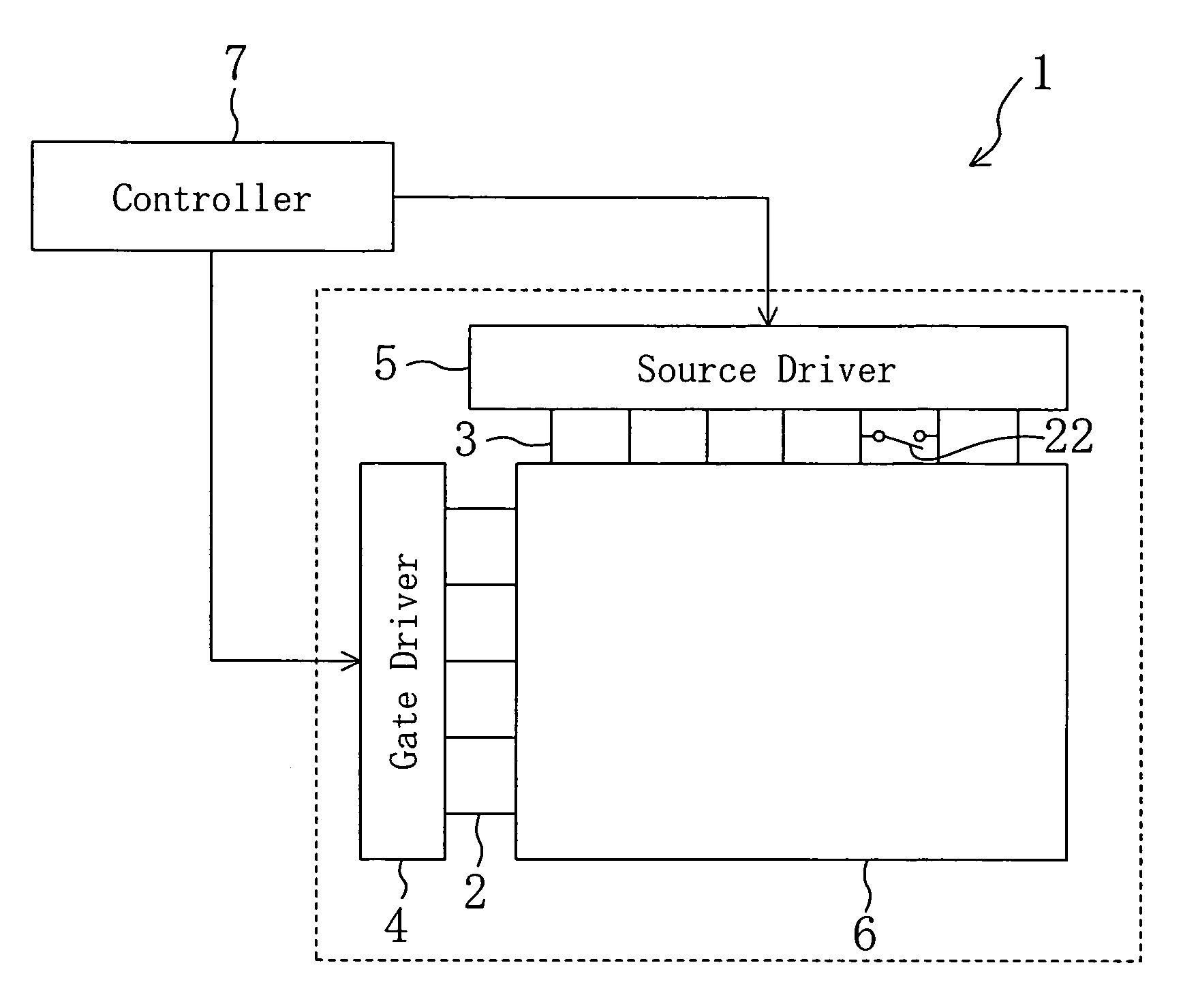
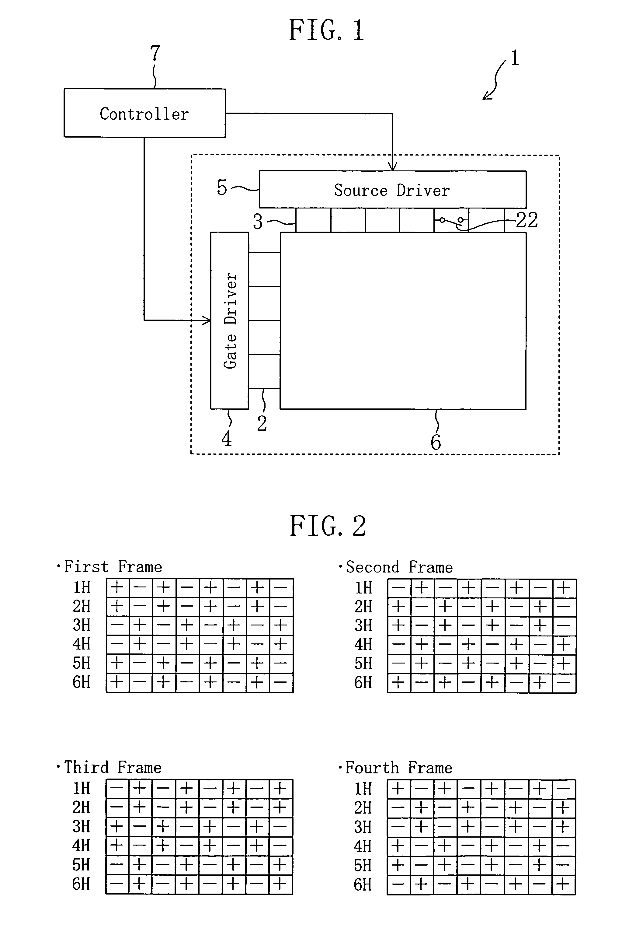
[0050]FIG. 1 schematically illustrates a liquid crystal display of the present embodiment.

[0051]As shown in FIG. 1, the liquid crystal display 1 of the present embodiment includes: a display panel 6, which is provided with sub-pixels each having a TFT and a liquid crystal capacitor, for displaying images; scanning lines 2 and signal lines 3, which are both provided within the display panel 6, for driving the sub-pixels; a gate driver 4 for supplying voltage to the scanning lines 2; a source driver 5 for supplying voltage to the signal lines 3; and a controller 7 for controlling the operations of the gate driver 4 and the source driver 5. The source driver 5 has an electrical charge recovering means 22 for connecting adjacent output sections for a certain period of time. The signal lines 3 and the scanning lines 2 intersect with...


PUM

PropertyMeasurementUnit
polarityaaaaaaaaaa
period of timeaaaaaaaaaa
output voltageaaaaaaaaaa

Abstract

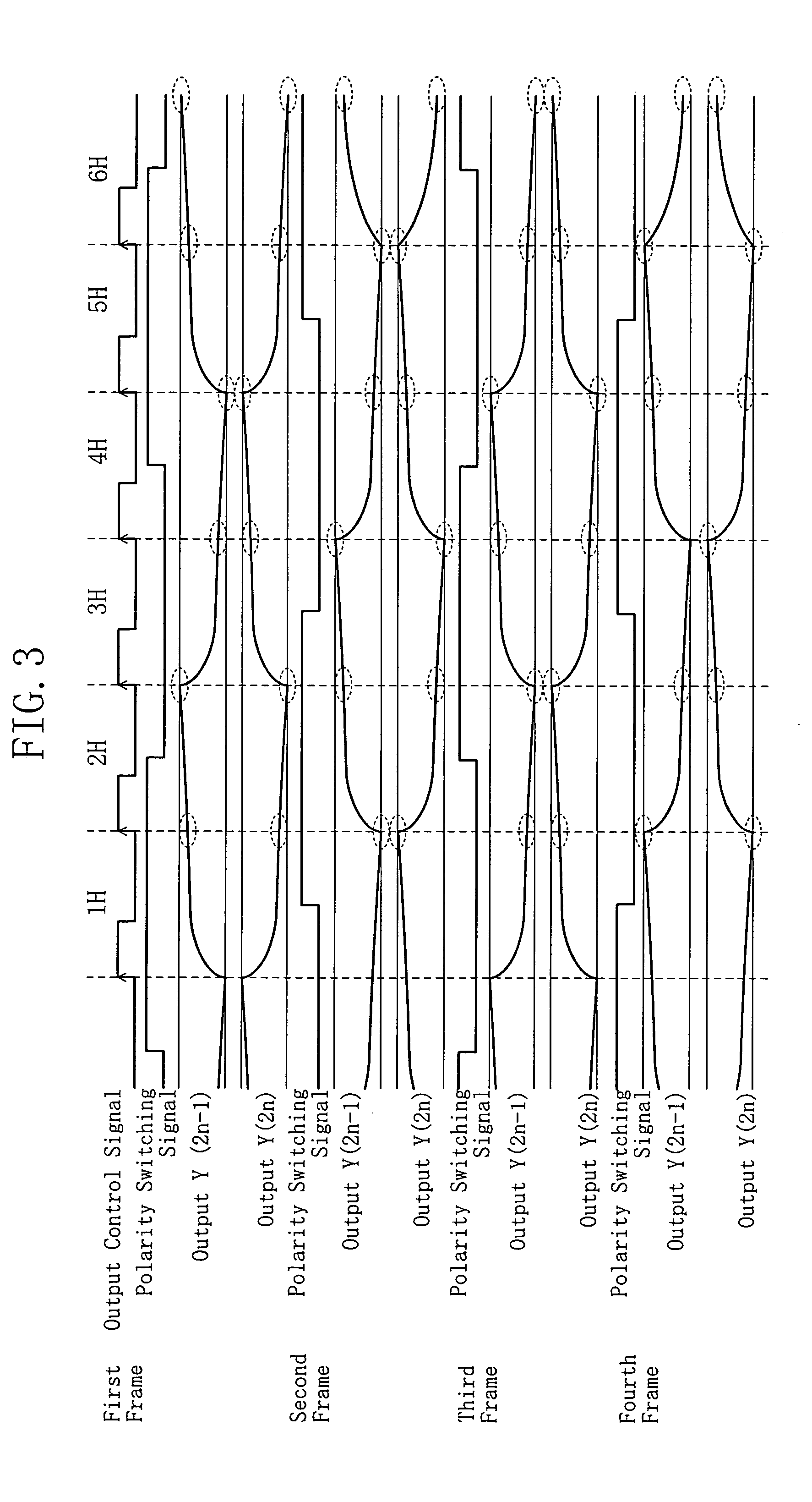
If a display is subjected to n line dot inversion drive control, the polarity pattern of sub-pixels is shifted line by line in a cycle of n frames. Furthermore, in every n horizontal scanning periods in which the polarities of output terminals of a source driver are switched, at least two of the output terminals are short-circuited to carry out electrical charge recovery. By using these methods, it is possible to achieve a reduction in power consumption while improving image quality.

Description

BACKGROUND OF THE INVENTION[0001]1. Field of the Invention[0002]The present invention relates to a display that employs a dot inversion drive scheme for a plurality of lines, and a method for driving the display.[0003]2. Prior Art[0004]A liquid crystal display (LCD) is smaller in power consumption than a cathode-ray tube or the like and does not occupy much space, and thus a liquid crystal display is now used as one of principal visual displays. Among them, an active matrix liquid crystal display using TFTs (thin-film transistors) achieves high resolution and is adaptable to a large screen, and therefore, an active matrix liquid crystal display has a wide range of applications such as a personal computer display and a TV screen.[0005]In each of active matrix displays, TFTs are arranged in a matrix pattern on a display panel. The operations of these TFTs are controlled by driver ICs that are normally provided at a frame portion of the display panel. The driver ICs include a source dr...

Claims


Application Information

Patent Timeline
Patent Type & Authority Patents(United States)
IPC IPC(8): G09G3/36G02F1/133G02F1/136G09G3/20G09G5/00
CPCG09G3/3614G09G3/3688G09G2330/023G09G2310/027G09G2320/0247G09G2310/0248G09G3/36
Inventor ASADA, TETSUOSARAI, OSAMU
Owner COLLABO INNOVATIONS INC
Learn More