Circuit and method for driving LED string for backlight, and backlight and display device using the circuit

a technology of led string and backlight, which is applied in the direction of static indicating devices, instruments, optics, etc., can solve the problems of gradual drop of driving voltage, and achieve the effect of suppressing screen flicker

Active Publication Date: 2012-11-01
ROHM CO LTD
View PDF1 Cites 21 Cited by
  • Summary
  • Abstract
  • Description
  • Claims
  • Application Information

AI Technical Summary

Benefits of technology

[0014]The present invention has been made in view of such a situation. Accordingly, it is an exemplary purpose of an embodiment of the present invention to provide a driving technique for a backlight LED which is capable of suppressing screen flicker.

Problems solved by technology

Thus, the driving voltage gradually falls over time.

Method used


Image

  • Circuit and method for driving LED string for backlight,  and backlight and display device using the circuit
  • Circuit and method for driving LED string for backlight,  and backlight and display device using the circuit
  • Circuit and method for driving LED string for backlight,  and backlight and display device using the circuit

Examples


first embodiment

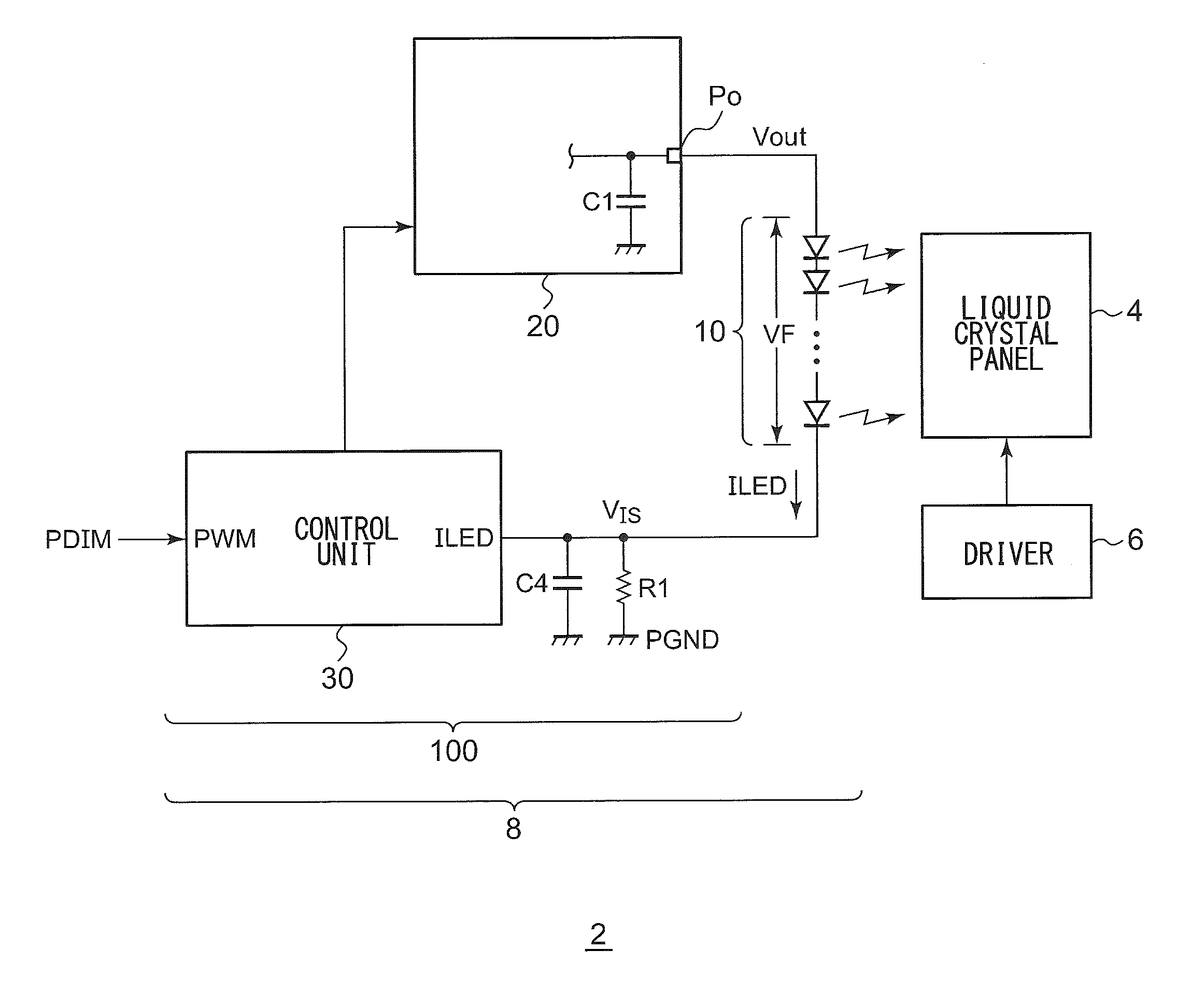
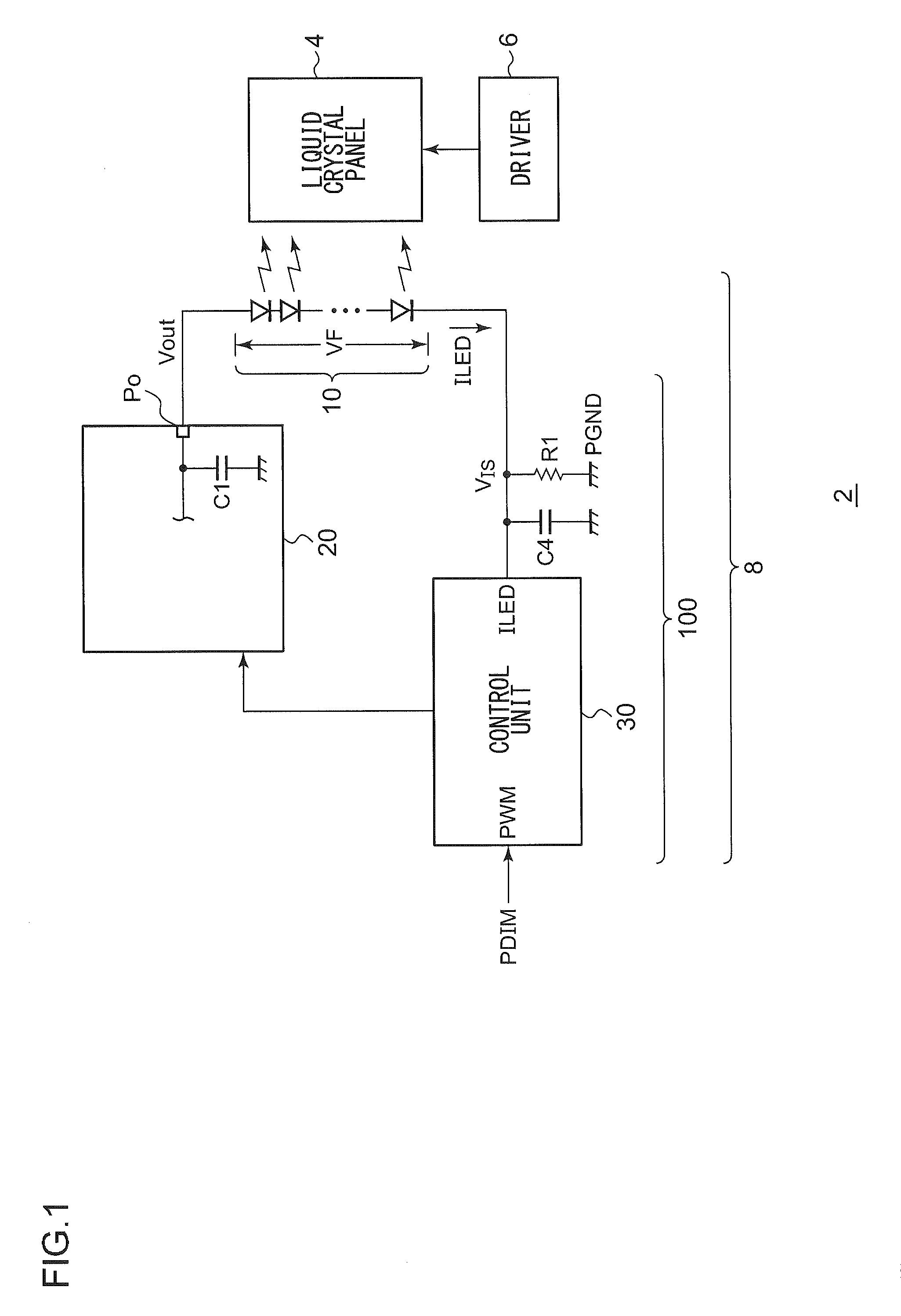
[0040]FIG. 1 is a circuit diagram which shows a configuration of a display apparatus 2 according to a first embodiment. The display apparatus 2 includes a liquid crystal panel 4, a liquid crystal driver 6, and a backlight 8.

[0041]The liquid crystal panel 4 includes multiple pixels arranged in the form of a matrix. The respective pixels are arranged at the points of intersection of the multiple data lines and the multiple scanning lines. The liquid crystal driver 6 receives image data to be displayed on the liquid crystal panel 4. The liquid crystal driver 6 includes a data driver which applies a driving voltage to the multiple data lines according to the luminance level, and a gate driver which sequentially selects the multiple scanning lines.

[0042]The backlight 8 is arranged on the back face of the liquid crystal panel 4. The backlight 8 includes an LED string 10 and a driving circuit 100 configured to drive the LED string 10.

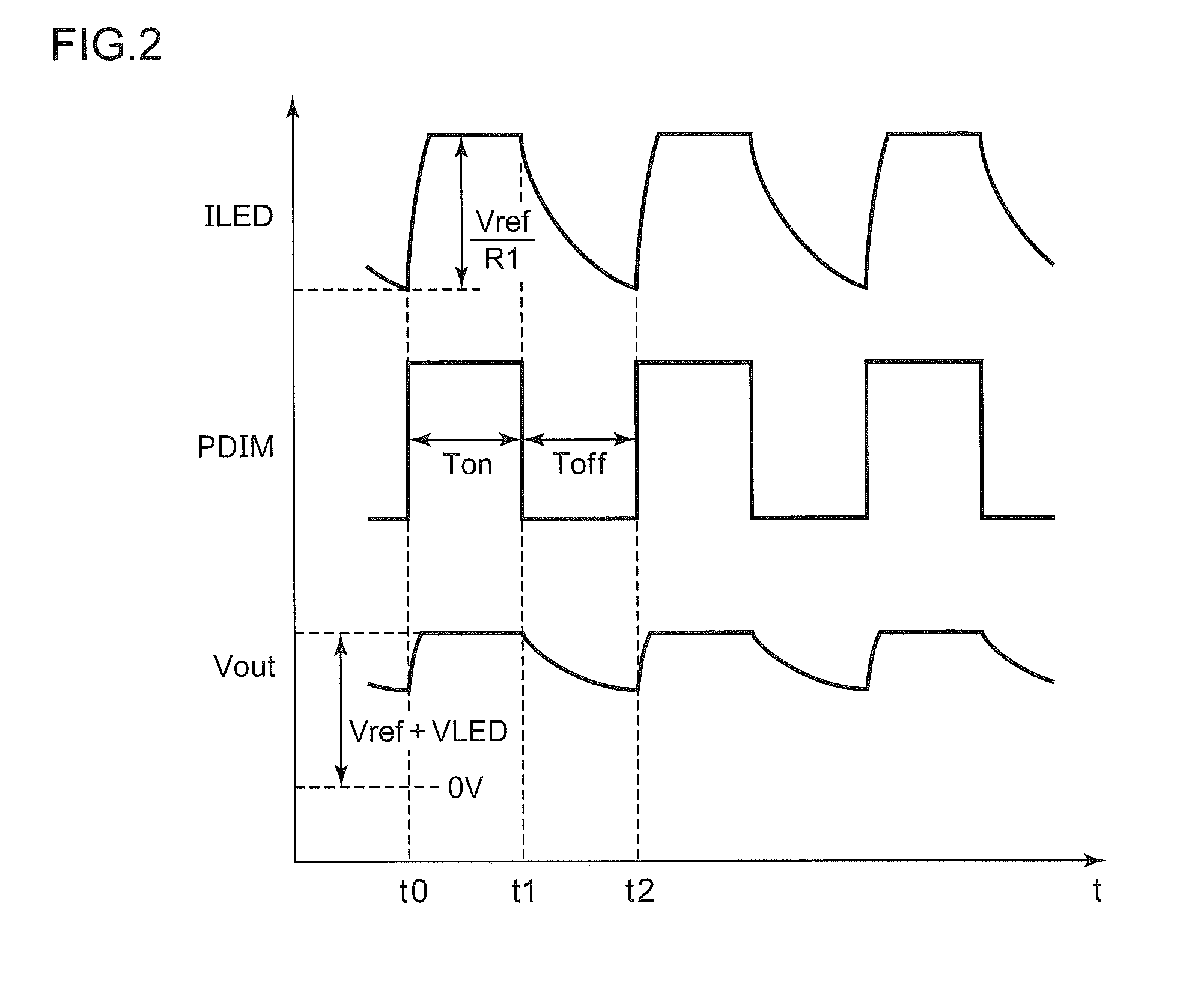
[0043]The backlight 8 controls the light-emission lumina...

second embodiment

[0093]FIG. 9 is a block diagram which shows a configuration of the backlight 8 according to a second embodiment. Description has been made in the first embodiment regarding an arrangement in which the waveform of the driving current ILED is dulled by means of discharging the output capacitor C1. In contrast, with the second embodiment, the driving current ILED (current detection signal VIS) is directly controlled.

[0094]An LED control IC 110a includes a pattern signal generating circuit 70 and a control unit 30a. The pattern signal generating circuit 70 receives a PDIM signal having a duty ratio that corresponds to the luminance. The pattern signal generating circuit 70 generates a reference voltage VA that transits to a first target value with a first slope upon receiving one kind of edge, i.e., either the positive edge or the negative edge, of the PDIM signal, and that transits to a second target value with a second slope upon receiving the other kind of edge. For example, upon rec...


PUM

PropertyMeasurementUnit
capacitanceaaaaaaaaaa
resistanceaaaaaaaaaa
frequencyaaaaaaaaaa

Abstract

An LED driving circuit drives a display backlight LED string including multiple LEDs connected in series. A power supply supplies a driving voltage from an output terminal thereof to a first end of the LED string. A detection resistor is arranged between a second end of the LED string and a fixed voltage terminal. The LED driving circuit receives a pulse modulation signal having a duty ratio that corresponds to the luminance. In the on period, in which the PDIM signal is the first level, the LED driving circuit controls the power supply such that the voltage drop across the detection resistor approaches a predetermined target value. In the off period, in which the PDIM signal is the second level, the LED driving circuit stops the control operation for the power supply.

Description

CROSS REFERENCE TO RELATED APPLICATIONS[0001]This is a U.S. national stage of application No. PCT / JP2010 / 006464, filed on 2 Nov. 2010. Priority under 35 U.S.C. §119(a) and 35 U.S.C. §365(b) is claimed from Japanese Application No. 2009-252861, filed 4 Nov. 2009, the disclosure of which are also incorporated herein by reference.BACKGROUND OF THE INVENTION[0002]1. Field of the Invention[0003]The present invention relates to a driving technique for a light emitting diode.[0004]2. Description of the Related Art[0005]As a backlight for a liquid crystal panel, white light emitting diodes (which will be simply referred to as “LEDs” hereafter) having improved properties from the perspective of a long operating life, low power consumption, and a wide color range are employed instead of conventional CCFLs (Cold Cathode Fluorescent Lamps) or EEFLs (External Electrode Fluorescent Lamps).RELATED ART DOCUMENTSPatent Documents[Patent Document 1][0006]Japanese Patent Application Laid Open No. 2004-...

Claims


Application Information

Patent Timeline
Patent Type & Authority Applications(United States)
IPC IPC(8): H05B37/02G02F1/13357
CPCG09G3/3406G09G2310/066G09G2320/0247G09G2320/064H05B33/089G09G2330/04H05B33/0815Y02B20/346H05B33/0848G09G2330/02H05B45/14H05B45/50Y02B20/30H05B45/38H05B45/3725H05B45/395H05B45/59
Inventor SASAKI, YOSHIKAZUFUKUMOTO, KENICHI
Owner ROHM CO LTD
Why Eureka
Try Eureka