Electrode and connecting designs for roll-to-roll format flexible display manufacturing

a flexible display and connecting design technology, applied in the direction of non-linear optics, static indicating devices, instruments, etc., can solve the problems of difficult maintenance, costly and difficult, and difficult on-line inspection of the electrode continuity of the electrode lines aligned with the web direction, etc., to achieve convenient installation and maintenance, and more reliable

Inactive Publication Date: 2008-02-05
E INK CALIFORNIA
View PDF29 Cites 54 Cited by
  • Summary
  • Abstract
  • Description
  • Claims
  • Application Information

AI Technical Summary

Benefits of technology

[0015]The fourth aspect of the present invention is directed to a novel connecting system for a display module. The system does not need precision bonding of the display panel to a driver circuitry and is more reliable and easier to install and maintain.

Problems solved by technology

However, this process has many disadvantages.
In addition, electrode lines aligned in the web direction are difficult to manufacture and easy to break during the roll-to-roll process.
Furthermore, the on-line inspection for the electrode continuity of the electrode lines aligned with the web direction is also difficult.
The connecting system of a flat panel display typically involves either precision bonding or complicated mechanical devices, which are costly and difficult to maintain.
Printing new tags and placing them at the proper locations is a very labor-intensive and costly process.
In fact, it is one of the major operation costs for most stores.
However, both types of display are bulky and very power demanding, and therefore are difficult to be integrated into the shelf structures in the stores.
They also require a complicated wiring system to connect the panel to the driver and controller circuitries.
LCD and LED are also fragile and difficult to maintain.

Method used


Image

  • Electrode and connecting designs for roll-to-roll format flexible display manufacturing
  • Electrode and connecting designs for roll-to-roll format flexible display manufacturing
  • Electrode and connecting designs for roll-to-roll format flexible display manufacturing

Examples


Embodiment Construction

Technical Background

Preparation of Micro-Cup Based Display Panel

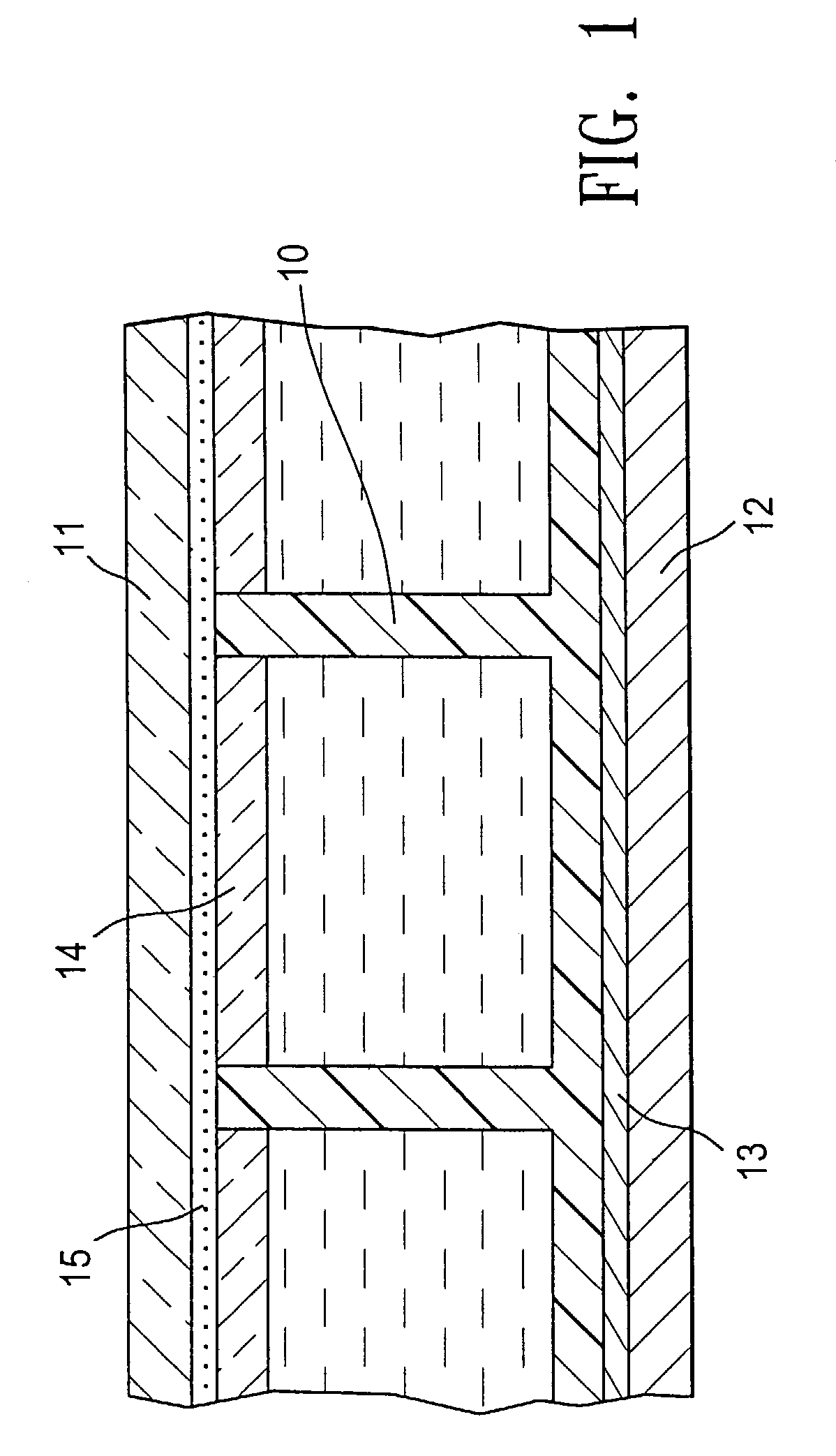
[0024]FIG. 1 depicts a typical display cell prepared by the microcup technology as disclosed in WO01 / 67170. The microcup-based display cell (10) is sandwiched between a first electrode layer (11) and a second electrode layer (12). A primer layer (13) is optionally present between the cell and the second electrode layer (12). The cell (10) is filled with an electrophoretic fluid and sealed with a sealing layer (14). The first electrode layer (11) is laminated onto the sealed cell optionally with an adhesive (15).

[0025]The display panel may be prepared by microembossing or photolithography as disclosed in WO01 / 67170. In the microembossing process, an embossable composition is coated onto the conductor side of the second electrode layer (12) and embossed with a male mold to produce arrays of microcups. To improve the mold release property, the conductor layer may be pretreated with a thin primer layer (13) before coating t...


PUM

PropertyMeasurementUnit
angleaaaaaaaaaa
angleaaaaaaaaaa
angleaaaaaaaaaa

Abstract

The present invention generally is directed to electrode designs suitable for roll-to-roll format flexible manufacturing of an EPD. It is also directed to an EPD having a segment design in a repeated pattern across an entire roll of the display. The EPD preferably is microcup-based. The EPD manufactured according to the present invention has the appearance of a roll of wall paper and it can be cut into any desired sizes or formats. The EPD has electrode or trace lines which may be exposed by asymmetrical cutting and stripping without the need of precision registration.

Description

RELATED APPLICATIONS[0001]This application claims the benefit of U.S. Provisional Application No. 60 / 385,053 filed May 29, 2002, which is incorporated herein by reference in its entirety.BACKGROUND OF THE INVENTION[0002]An electrophoretic display (EPD) is a non-emissive device based on the electrophoresis phenomenon influencing charged pigment particles suspended in a colored dielectric solvent. This type of display was first proposed in 1969. An EPD typically comprises a pair of opposed, spaced-apart plate-like electrodes, with spacers predetermining a certain distance between the electrodes. At least one of the electrodes, typically on the viewing side, is transparent.[0003]When a voltage difference is imposed between the two electrodes, the pigment particles migrate by attraction to the plate of polarity opposite that of the pigment particles. Thus, the color showing at the transparent plate, determined by selectively charging the plates, can be either the color of the solvent or...

Claims


Application Information

Patent Timeline
Patent Type & Authority Patents(United States)
IPC IPC(8): G09G3/34G02F1/1333G02F1/1343G02F1/167G02F1/1676G02F1/1679
CPCG02F1/134327G02F1/167G02F1/133305G02F1/134336G02F2001/1672G02F2001/1676G02F1/1676G02F1/1681G02F1/1679
Inventor CHUNG, JERRYHOU, JACKLIANG, RONG-CHANG
Owner E INK CALIFORNIA
Why Eureka
Try Eureka