Nematic liquid crystal display device with multi-domain pixels and six phase difference compensators

a liquid crystal display and multi-domain technology, applied in non-linear optics, instruments, optics, etc., can solve the problems of reducing the aperture ratio and thus the transmissivity (brightness) of the device, reducing production efficiency, and reducing production efficiency, so as to achieve the desired viewing angle characteristics without sacrificing production efficiency and transmissivity

Inactive Publication Date: 2008-02-05
SHARP KK
View PDF28 Cites 7 Cited by
  • Summary
  • Abstract
  • Description
  • Claims
  • Application Information

AI Technical Summary

Benefits of technology

[0026]Thus, the invention described herein makes possible the advantage of providing a liquid crystal display de

Problems solved by technology

In the IPS mode ①, however, it is necessary to provide a plurality of opaque electrodes in a pixel, thereby reducing the aperture ratio and thus the transmissivity (brightness) of the device.
In such a case, the liquid crystal injection process takes a period of time twice as long as that for a device which employs a p-type liquid crystal material having a positive dielectric anisotropy and a substrate which has been subjected to a horizontal alignment process, thereby reducing the production efficiency.
Moreover, The liquid crystal display device ③ employs a liquid crystal material having a positive dielectric anisotropy and a substrate

Method used


Image

  • Nematic liquid crystal display device with multi-domain pixels and six phase difference compensators
  • Nematic liquid crystal display device with multi-domain pixels and six phase difference compensators
  • Nematic liquid crystal display device with multi-domain pixels and six phase difference compensators

Examples


example 1

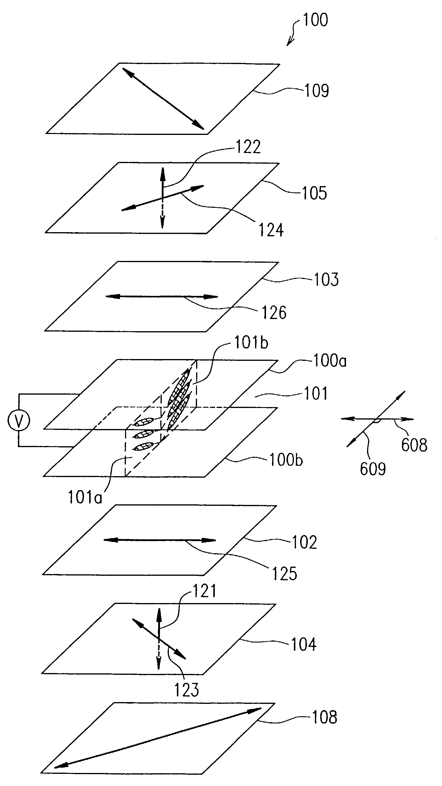
[0175]FIG. 4 illustrates Example 1 of the present invention. FIG. 4 illustrates the liquid crystal cell 101, the phase plates 102, 103, 104 and 105, and polarizing plates 108 and 109.

[0176]Each pixel in the liquid crystal cell 101 is divided into two regions A and B having different orientations. Orientation parameters for the respective regions are as follows.

[0177]

TABLE 2Area in percent forRetardationRegionthe entire pixelvalueTwist angleOrientationA50%240 nm0 deg 90 degB50%240 nm0 deg270 deg

[0178]Parameters for the polarizing plates are as follows.

[0179]

TABLE 3Ref # ofAngle ofpolarizing platetransmission axis108  45 deg109−45 deg

[0180]Parameters for the phase plates are as follows.

[0181]

TABLE 4Ref # ofAngle ofphase plated*(na–nb)d*(na–nc)na axis102120 nm   0 nm   0 deg103120 nm   0 nm   0 deg104 57 nm−72 nm−45 deg105 57 nm−72 nm  45 deg

[0182]FIG. 12 illustrates an isocontrast diagram based on values (contrast ratios) obtained by dividing the transmissivity for an applied voltage ...

example 2

[0191]In this example, various parameter ranges in which the phase difference compensators 104 and 105 function effectively were estimated. The parameters include the in-plane retardation d·(na−nb), the retardation along the thickness direction d·(na−nc), and the angle of the na axis. First, preferred ranges for the retardation values of the phase difference compensators d·(na−nb) and d·(na−nc) will be estimated.

[0192]Before estimating the parameter ranges, parameters RL and NZ will be defined as follows, with which the parameter ranges can be uniquely determined and compared with the retardation value (dlcΔn) of the liquid crystal layer.

RL=d·(na−nc) / (dlcΔn)

NZ=(na−nc) / (na−nb)

[0193]The influence of the retardation was examined using a liquid crystal display device similar to that of Example 1. It was assumed that the parameters of the phase difference compensators 104 and 105 are equal to each other, and the parameters were varied in the following ranges.

0<|RL|<1 and RL<0

0.1<|NZ|<100...

example 3

[0271]A liquid crystal display device 1800 according to Example 3 of the present invention will be schematically illustrated with reference to FIG. 18. FIG. 18 illustrates a liquid crystal cell 101, phase plates 102, 103, 104, 105, 110 and 111, and polarizing plates 108 and 109.

[0272]The liquid crystal cell 101 in each pixel is divided into two regions A and B having different orientations. The orientation parameters for the regions are as follows.

[0273]

TABLE 9Area in percent forRetardationRegionthe entire pixelvalueTwist angleOrientationA50%261 nm0 deg 90 degB50%261 nm0 deg270 deg

[0274]Parameters for the polarizing plates are as follows.

[0275]

TABLE 10Ref # ofAngle ofpolarizing platetransmission axis108  45 deg109−45 deg

[0276]Parameters for the phase plates are as follows.

[0277]

TABLE 11Ref # ofAngle ofphase plated*(na–nb)d*(na–nc)na axis102130 nm   0 nm   0 deg103130 nm   0 nm   0 deg104 0 nm−131 nm   0 deg105 0 nm−131 nm   0 deg110 29 nm   0 nm−45 deg111 29 nm   0 nm  45 deg

[0278]F...


PUM


Abstract

Featured is a liquid crystal display device including first and second transparent substrates and a liquid crystal layer interposed there between that includes a plurality of domains in each pixel region. Also included are first and second polarizing plates and first and second phase compensators; the first compensator is provided between the first polarizing plate and first substrate and the second compensator is between the second polarizing plate and second substrate. The phase-delay axes for the first and second compensators are parallel to each other and substantially perpendicular to a phase-delay axis of the liquid crystal layer. A third phase difference compensator is provided between the first and/or second polarizing plate and the corresponding first or second compensator.

Description

[0001]This application is a continuation of U.S. application Ser. No. 09 / 342,776, filed Jun. 29, 1999, now U.S. Pat. No. 6,650,386, the teachings of which are incorporated herein by reference in its entirety.BACKGROUND OF THE INVENTION[0002]1. Field of the Invention[0003]The present invention relates to a liquid crystal display device as a computer monitor and a liquid crystal display device for displaying video images and, more particularly, to a liquid crystal display device having desirable viewing angle characteristics.[0004]2. Description of the Related Art[0005]Various display modes have been proposed for improving the viewing angle of a liquid crystal display device. Typical examples of such display modes include: ① IPS (In-Plane Switching) mode which uses a transverse electric field to move the liquid-crystal molecules in parallel with the substrate surface; ② a liquid crystal display device in which the liquid crystal molecules are oriented substantially vertically to the s...

Claims


Application Information

Patent Timeline
IPC IPC(8): G02F1/1335G02F1/13363G02F1/1347G02F1/1343G02F1/139
CPCG02F1/133634G02F1/134363G02F1/1393G02F1/1347
Inventor SHIMOSHIKIRYOH, FUMIKAZU
Owner SHARP KK
Why Eureka
Try Eureka