Winding core and associated method

a core and core technology, applied in the field of winding cores, can solve the problems of affecting the performance of the core, the engaged end of the paperboard roll is subjected to substantial torque force, and the cores are not compatible with existing winding and unwinding machinery, so as to improve the gripping surface, reduce the risk of slippage, and increase the chuck factor

Inactive Publication Date: 2007-04-17
SONOCO DEV INC
View PDF23 Cites 4 Cited by
  • Summary
  • Abstract
  • Description
  • Claims
  • Application Information

AI Technical Summary

Benefits of technology

[0011]The invention addresses the above needs and achieves other advantages by providing a winding core with an improved gripping surface for a chuck and increased chuck factor. A chuck-engaging layer is disposed on a portion of the inner surface of the core member to provide a gripping surface to allow the chuck to engage the winding core in a manner less susceptible to slippage between the chuck and core. In addition, a combination of the chuck-engaging layer, a longer winding core, and a longer chuck can allow the winding core to wind and unwind more material at traditional winding speeds without increasing the winding core outer diameter substantially or sacrificing efficiency and safety.
[0019]The winding core assembly of the present invention advantageously provides for an improved winding core having a chuck-engaging layer applied to its inner surface, which enables chucks on either end of the winding core to grip the chuck-engaging layer. The chuck-engaging layer is softer than the winding core material, such that the chuck can penetrate the chuck-engaging layer and create increased friction due to better contact with the winding core surface to prevent the chuck from slipping while the winding core is rotating.
[0020]The winding core assembly also can decrease the incidence of chew out, as the chucks are able to grip the chuck-engaging layer lining the inner surface of the winding core. In addition, the chuck factor of the winding core is increased, which correspondingly allows the safety factor to be increased. Increasing the safety factor ensures that the winding core may be rotated at higher than typical winding speeds without risking excessive vibration.
[0021]Winding cores in accordance with the present invention can be much longer than typical winding cores, which permits an increased amount of material to be wound. Also, the chucks preferably are longer to adequately grip the longer and heavier winding core. The combination of the chuck-engaging layer, longer winding core, and longer chucks allows the winding core to wind and unwind more material at current winding speeds without increasing the winding core outer diameter substantially or sacrificing efficiency.

Problems solved by technology

A potential solution to the problem is to increase core stiffness by increasing core diameter, but this would be undesirable if it meant that the cores would not be compatible with existing winding and unwinding machinery, as would be the case if the inside diameter of the core were increased.
The rolls of material are often subjected to substantial circumferential acceleration and deceleration by the winding machines.
This, in turn, subjects the engaged ends of the paperboard roll to substantial torque forces.
This often leads to some slippage of the chuck on the inside of the core.
In an extreme situation, the slippage can lead to “chew-out” wherein the core is essentially destroyed by the chuck.
Aside from problems such as chew-out, the failure of the chuck to firmly grip the core can lead to other undesirable effects.

Method used


Image

  • Winding core and associated method
  • Winding core and associated method
  • Winding core and associated method

Examples


Embodiment Construction

[0026]The present invention now will be described more fully hereinafter with reference to the accompanying drawings, in which some, but not all embodiments of the invention are shown. Indeed, this invention may be embodied in many different forms and should not be construed as limited to the embodiments set forth herein; rather, these embodiments are provided so that this disclosure will satisfy applicable legal requirements. Like numbers refer to like elements throughout.

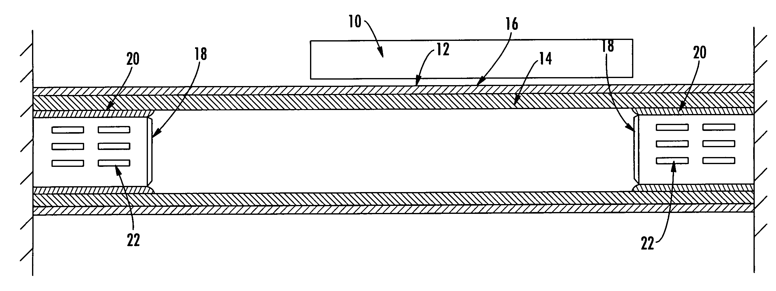
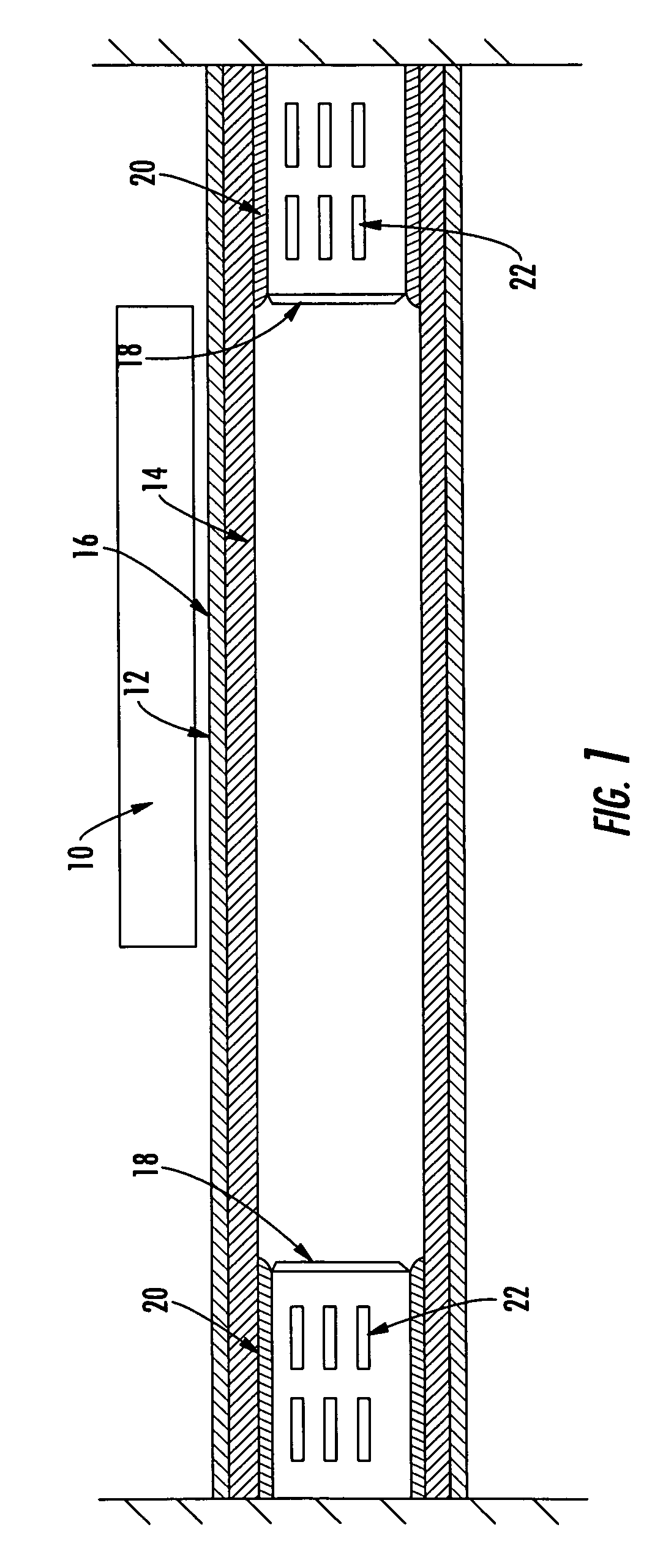
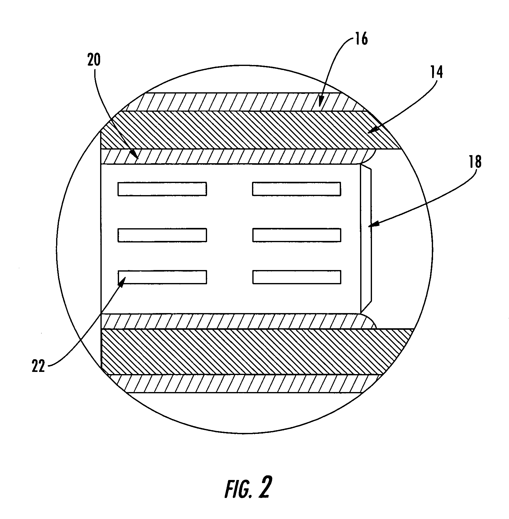
[0027]Referring now to the drawings and, in particular to FIG. 1, there is shown a winding core assembly 10. The term “winding core” is not meant to be limiting, and it is understood that the term winding core can be any core, reel, tube, cylinder, or the like used in a winding operation. Winding may be used to wind and unwind rolls of web materials such as polymer film, paper, nonwoven or woven textile, metal foil, sheet metal, and the like.

[0028]In a preferred embodiment, FIG. 1 illustrates that the winding core...


PUM


Abstract

A winding core, a winding core assembly for winding web materials, and a method are provided. The winding core includes a hollow cylindrical core member having an inner surface, an outer surface, and first and second ends. A chuck-engaging layer is located on the inner surface of the core member, wherein the chuck-engaging layer is softer than the core member.

Description

BACKGROUND OF THE INVENTION[0001]1. Field of the Invention[0002]The present invention relates to winding cores and, more particularly, to winding sheets of paper, film, and the like into large rolls and a method of winding such sheets onto a core.[0003]2. Description of Related Art[0004]Web materials such as polymer film, paper, nonwoven or woven textile, metal foil, sheet metal, and others, are used to manufacture a variety of products. The web materials are generally provided in the form of large rolls formed by winding the web material about a winding core. The core is generally paperboard, though it may be reinforced with a plastic outer shell or the like. The paperboard may be formed of high strength, high density paperboard plies. A roll of paper or the like wound onto the core typically has a weight above two tons and often exceeding five tons. Typical core sizes are an internal diameter of 3 in. (76.2 mm.) to 6 in. (152.0 mm.) or 150.4 mm. in Europe, and a length of about 10...

Claims


Application Information

Patent Timeline
Patent Type & Authority Patents(United States)
IPC IPC(8): B65H75/14B65H18/02B65H75/10B65H75/30
CPCB65H18/02B65H75/10B65H75/30
Inventor VAN DE CAMP, WIM
Owner SONOCO DEV INC
Why Eureka
Try Eureka