Check patentability & draft patents in minutes with Patsnap Eureka AI!

System for collision avoidance of rotary atomizer

a technology of collision avoidance and rotary atomizer, which is applied in the field of collision avoidance system of rotary atomizer, can solve the problems of reducing the mechanical reaction of collision disturbance force on the drive, affecting the speed of the motor shaft, and slowing or inhibiting the robot's movement,

Inactive Publication Date: 2008-02-05
DURR SYST INC
View PDF67 Cites 7 Cited by
  • Summary
  • Abstract
  • Description
  • Claims
  • Application Information

AI Technical Summary

Benefits of technology

"The invention is about calculating an error signal to recognize collisions by measuring the motion of a driven mechanism on both the driven side and the drive side. This can be useful in applications where motion detection is important."

Problems solved by technology

Here, however, the force merely leads to slow or inhibit robot motion.
However, in each case, the motion quantities of the drive, such as the angular position and the rpm of the motor shaft, deviate at least for a short time from the disturbance-free values.
However, a disadvantage of this known monitoring method for collision recognition is that the mechanical reaction of a collision disturbance force on the drive is strongly reduced by interposed gears.
Another disadvantage of known monitoring methods is that incorrect models for the drive lead to large errors, because the reaction of the mechanism to the drive is then set incorrectly.
Finally, another disadvantage of known monitoring methods is that the angular position is measured on the drive side, while the acceleration is calculated by differentiating the measured value twice.
This second derivative of the measured value leads to a very noisy signal.

Method used


Image

  • System for collision avoidance of rotary atomizer
  • System for collision avoidance of rotary atomizer
  • System for collision avoidance of rotary atomizer

Examples


Embodiment Construction

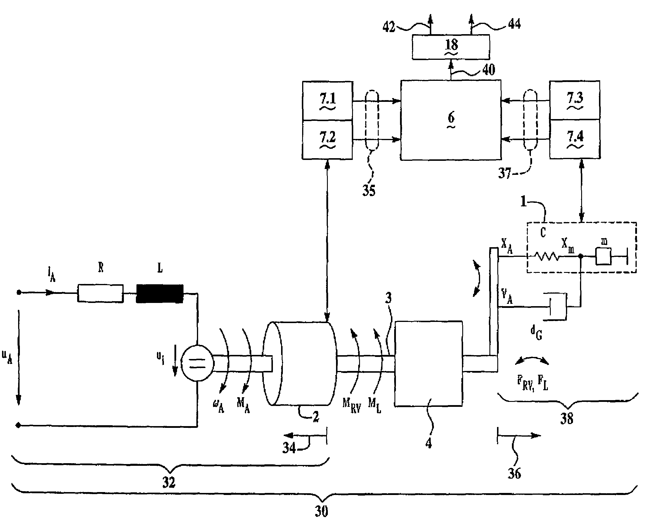
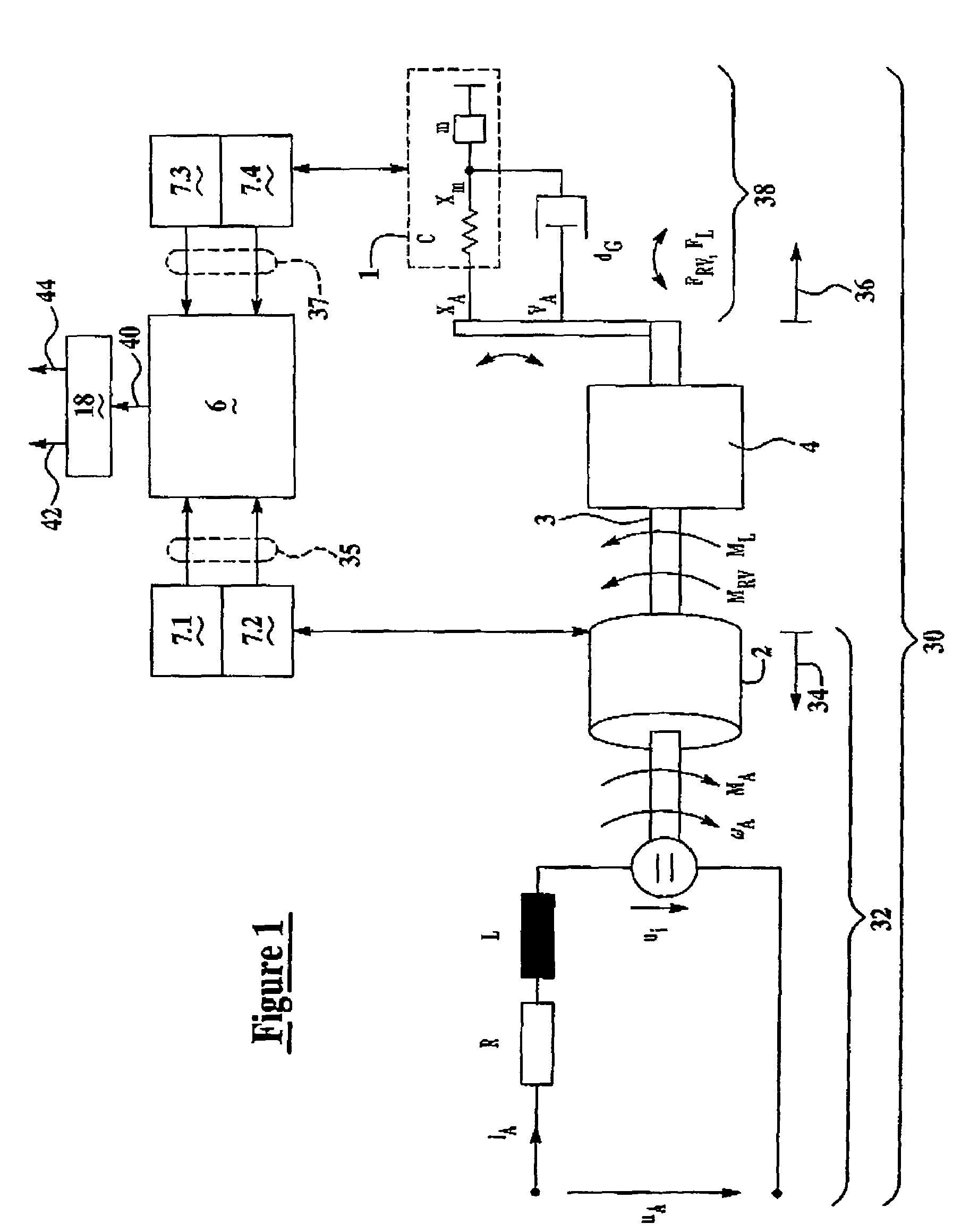
[0016]Referring to FIG. 1 and for determining a system error signal, the invention includes the general technical teaching of not only measuring drive-side (as indicated generally by arrow 34) motion quantities 35 of the drive system 30 preferably having a direct current motor 32, but also motion quantities 37 on the driven side (as indicated by arrow 36), i.e., on a driven mechanism 38.

[0017]One advantage of measuring motion quantities 35, 37 on the driven side 36 and the drive side 34 is the fact that the determination of the error signal corresponding to a collision is more accurate. For example, gears 4 interposed between the driven side 36 and the drive side 34 can prevent the communication of collision forces to sensors 7.1, 7.2 disposed on the drive side 34. Thus, the monitoring method for collision recognition according to the present invention can also be used for drive systems 30 which have gears 4 with a high transmission factor.

[0018]Another advantage of the monitoring m...


PUM


Abstract

A monitoring method for a drive system with a motor and a moving part driven by the motor. The movement of the driven part is monitored and the movement of the driving part is monitored and compared to recognize a collision between the driven part and another structure. Measurement of at least one drive-side motion quantity of the motor is taken and measurement of at least one driven-side motion quantity of the moving part is taken. The motion quantity can be a position, velocity or acceleration. A dynamic model is calculated based on predetermined or expected operational data and the drive side measured data. An error signal is generated when the motion quantity measured on the driven side varies from the dynamic model.

Description

[0001]This application is a continuation of U.S. application Ser. No. 10 / 895,430, filed Sep. 24, 2003 now abandoned.BACKGROUND OF THE INVENTION[0002]1. The Field of the Invention[0003]The invention concerns a monitoring method for a drive system with a motor and a moving part driven by a motor and more specifically to a system for detecting collisions between a moveable robot and other structure.[0004]2. Related Prior Art[0005]Painting systems for painting vehicle chassis include multi-axis painting robots. The robots include drive systems to control the position of a rotary atomizer. The drive systems include sensors and a controller that emits control signals to motors associated with the robot. The control signals are sent in response to signals received by sensors in accordance with a control program stored in the memory of the controller. The control program is prepared to achieve optimum painting results.[0006]Painting robots can be positioned adjacent other structures. A coll...

Claims


Application Information

Patent Timeline
Patent Type & Authority Patents(United States)
IPC IPC(8): G06F15/00B25J9/16G05B19/4061G05B19/4062
CPCB25J9/1674G05B19/4061G05B19/4062G05B2219/37297G05B2219/37624G05B2219/37625G05B2219/37632G05B2219/39186G05B2219/39355G05B2219/41372G05B2219/42161
Inventor HOOGE, SVENWILDERMUTH, DIETMAR
Owner DURR SYST INC
Features
  • R&D
  • Intellectual Property
  • Life Sciences
  • Materials
  • Tech Scout
  • Unparalleled Data Quality
  • Higher Quality Content
  • 60% Fewer Hallucinations
Learn More