Method and device for the pneumatic operation of a tool

a pneumatic operation and tool technology, applied in the direction of positive displacement liquid engine, fluid coupling, servomotor, etc., can solve the problems of only a large loss of heat to the environment, excessive amount of energy required for compressor operation, and heat loss affecting the energy efficiency negatively, so as to minimize the appearance of heat loss in the circuit

Active Publication Date: 2008-02-12
CARGINE ENG AB
View PDF5 Cites 56 Cited by
  • Summary
  • Abstract
  • Description
  • Claims
  • Application Information

AI Technical Summary

Benefits of technology

[0008]The object of the invention is to provide a method and a device to satisfy the need of pressure fluid, air or other gas for the operation of a tool while, simultaneously, the heat losses appearing in the circuit are minimized.
[0009]It is a further object of the invention to provide a method and a device that permits the use of the compressor with a relatively low capacity, that is a low consumption of air energy, for the operation of a specific tool.SUMMARY OF THE INVENTION
[0010]The invention is based on the conclusion that, if the required pressure fluid is generated through compression without the contemporary temperature increase, the heat losses can be reduced to a corresponding degree, and the compressor can be made substantially smaller, which in many cases is of important advantage.

Problems solved by technology

Normally, the transfer of heat to the environment is only a large loss of energy.
There are also other losses, but the far most important source of loss is constituted by said heat loss.
The heat loss effects the energy efficiency negatively.
An excessive amount of energy is required for the operation of a compressor for supplying, for example, pressurised air to a tool of a certain power.

Method used


Image

  • Method and device for the pneumatic operation of a tool
  • Method and device for the pneumatic operation of a tool
  • Method and device for the pneumatic operation of a tool

Examples


Embodiment Construction

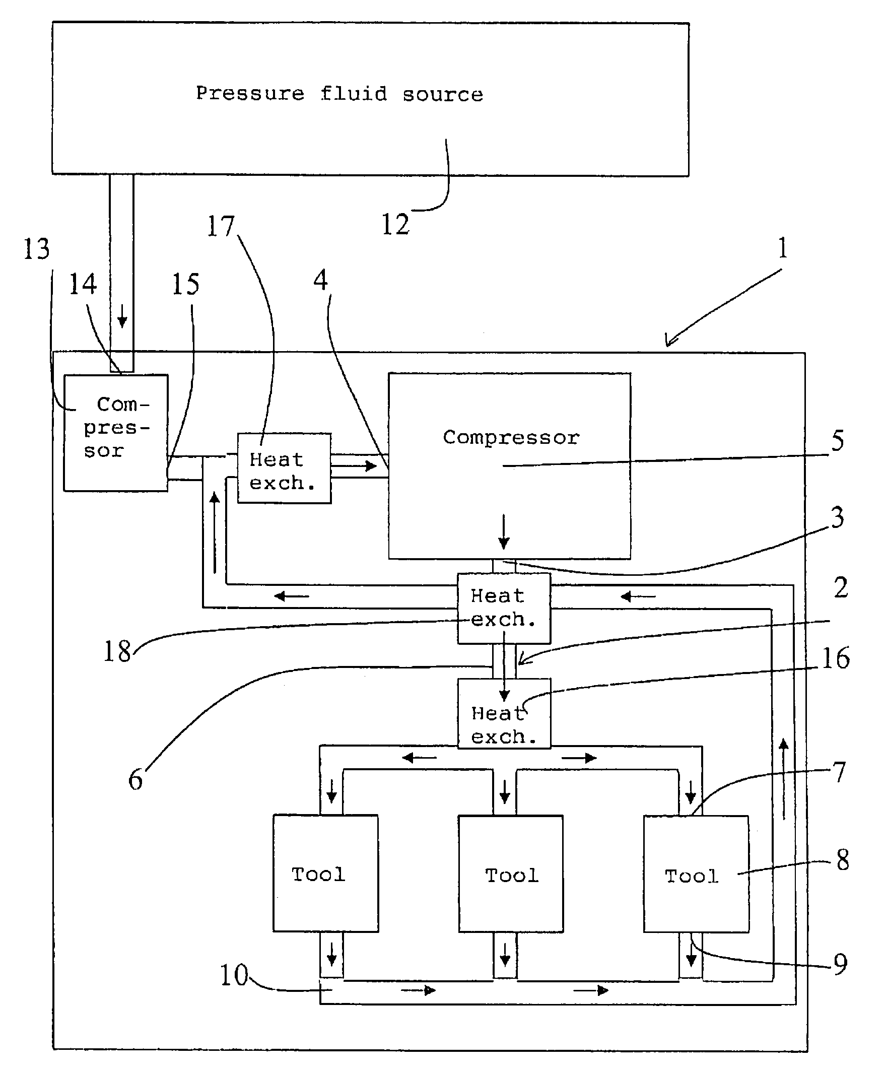
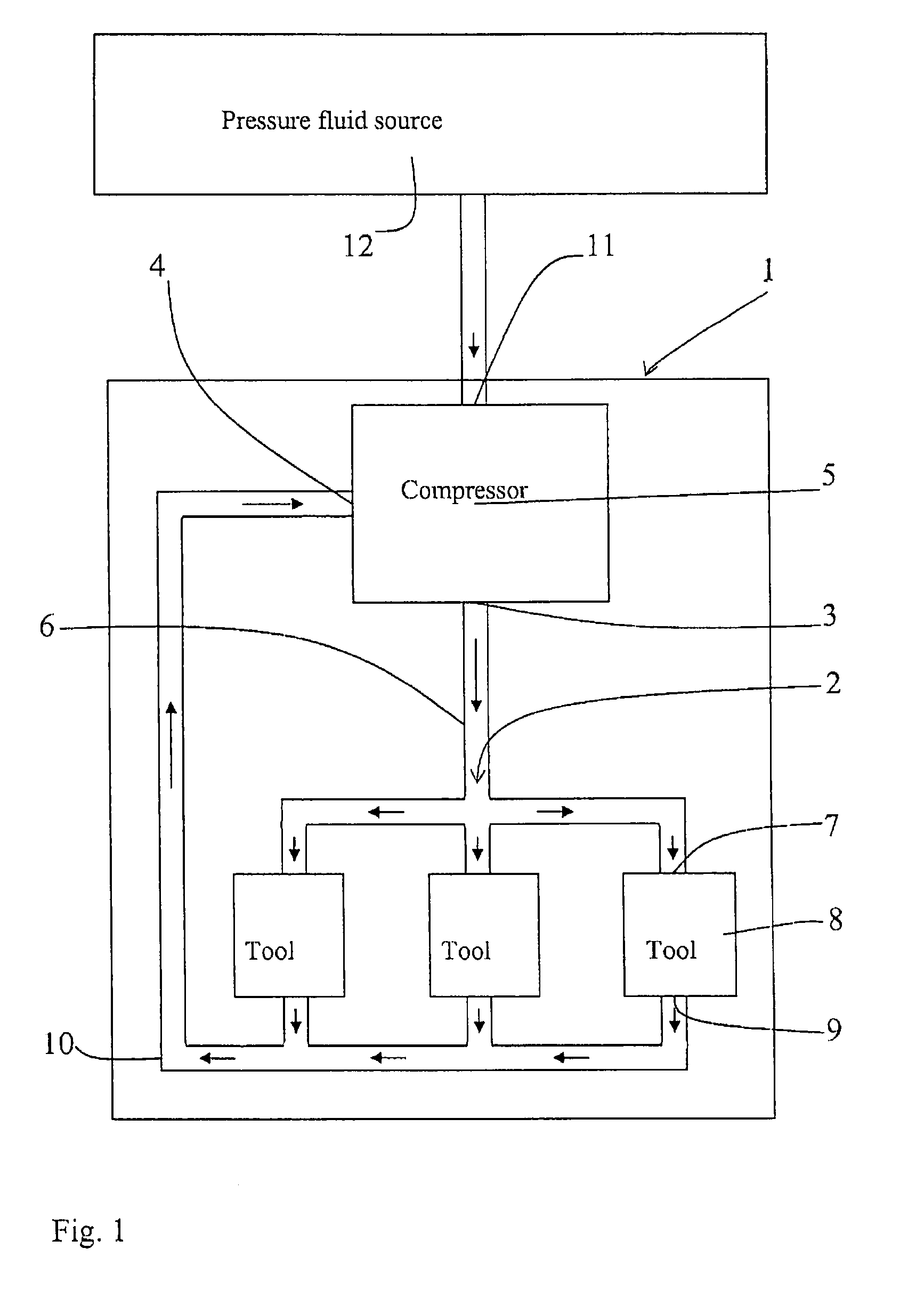
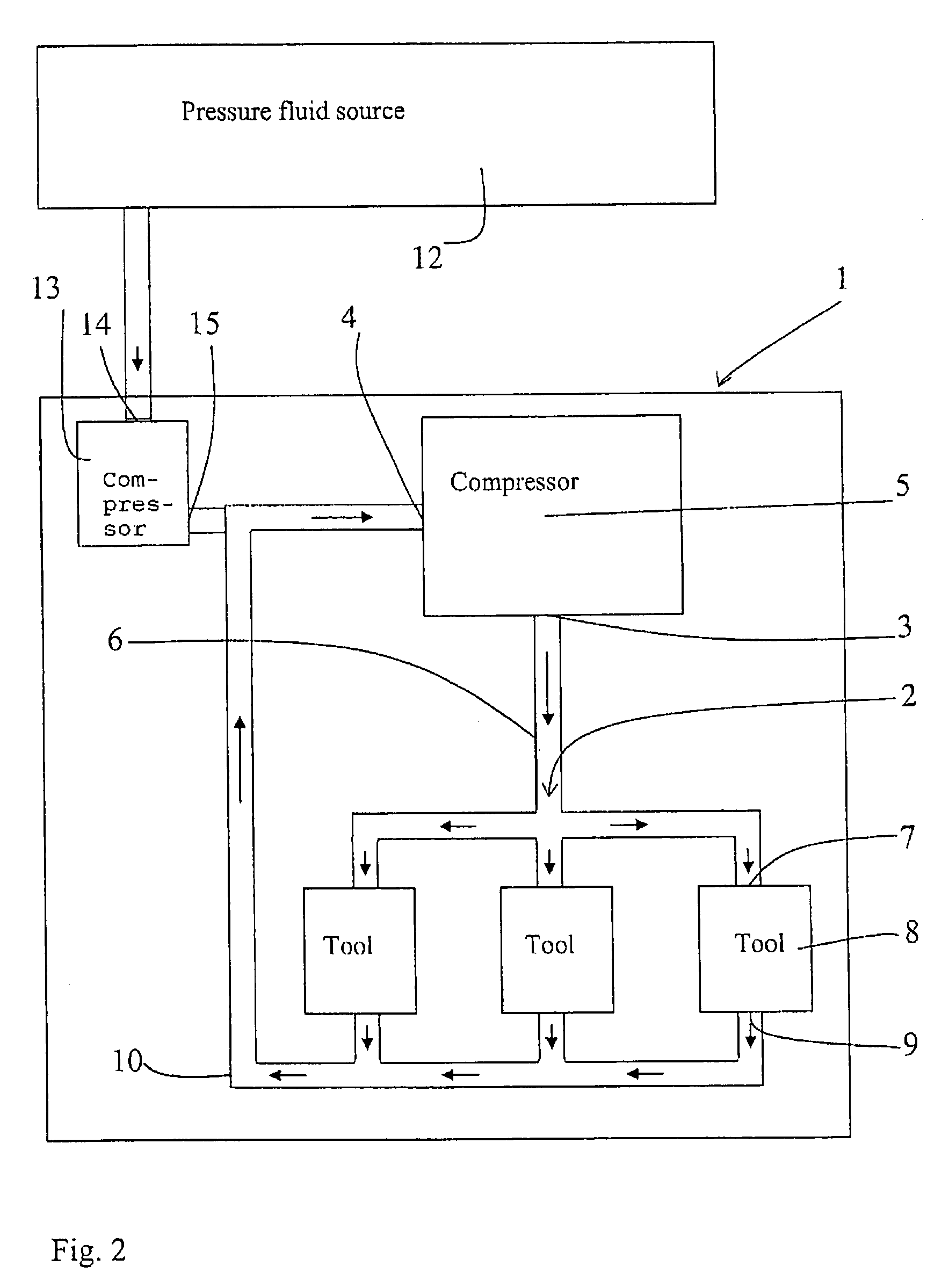
[0025]FIG. 1 shows a device 1 with a generally closed pressure fluid circuit 2 which comprises at least one compressor 5, that compresses and pumps fluid with a low compression ratio and a high pressure. The fluid is transported through the compressor 5 from the inlet 4 thereof to the outlet 3 thereof upon compression. The relation between the pressure at the outlet 3 and the pressure at the inlet 4 is, for a certain absolute increase of pressure in the compressor, remarkably low in comparison to contemporary methods / devices, as the pressure at the inlet 4 exceeds the pressure of the surrounding atmosphere, and since contemporary devices operate with an inlet pressure that generally corresponds to the pressure of the surrounding atmosphere. Preferably, the inlet pressure is more than 1,5 times, preferably more than 2,0 times higher than the pressure of the surrounding atmosphere.

[0026]The fluid is guided from the compressor 5 through a conduit 6 to an inlet 7 of at least one fluid-o...


PUM


Abstract

A device for the pneumatic operation of a tool includes a generally closed pressure fluid circuit (2), at least one compressor (5), for increasing the pressure of the pressure fluid in the circuit, the compressor (5) having an inlet and an outlet, and a tool driven by the pressure fluid in the circuit, and through which the pressure fluid is transported in the circuit from the outlet to the inlet of the compressor (5). The pressure that is generated by the compressor and the load adopted by the tool (8) are adapted such that the pressure of the returning pressure fluid downstream the tool (8) is higher than the pressure of the surrounding atmosphere.

Description

FIELD OF THE INVENTION[0001]The present invention relates to a method for the pneumatic operation of a tool.[0002]The invention also relates to a device for the implementation of the method.[0003]The invention is applicable at all kinds of pneumatic devices, such as engines and tools that are operated by means of air or any other gas. Tool, as it is referred to here, should be regarded in a wide sense, including devices for any industrial use, for the pneumatic operation of vehicles, for pneumatically activated actuators for engine valves, all types of working tools etc.[0004]“Generally closed” is referred to as a circuit that is as closed as possible, that is a circuit by which there is a continuous pressure fluid conduit from the outlet of the compressor, through the operated tool to the inlet of the compressor. Preferably, such a circuit is free from deliberately arranged passages through which the pressure fluid could leak out to the surrounding atmosphere.THE BACKGROUND OF THE ...

Claims


Application Information

Patent Timeline
Patent Type & Authority Patents(United States)
IPC IPC(8): F04B49/00F15B11/06F15B1/26F15B21/14
CPCF15B1/265F15B11/06F15B21/14F04B2205/01F15B2211/62F15B2211/88F15B2211/8855F04B49/00
Inventor HEDMAN, MATS
Owner CARGINE ENG AB
Why Eureka
Try Eureka