Low emission thermal plant

Active Publication Date: 2008-02-12
CO2 CAPSOL
View PDF10 Cites 53 Cited by
  • Summary
  • Abstract
  • Description
  • Claims
  • Application Information

AI Technical Summary

Benefits of technology

[0027]According to the present invention a method for the generation of electric power from a carbonaceous fuel is provided, in which the fuel is combusted in the presence of oxygen under elevated pressure in a combustion chamber. The exhaust gas from the combustion is separated into one CO2 rich fraction which is treated so that it is not discharged to the environment, and one CO2 depleted fraction which is expanded over one or more turbines for operation of other processes and/or generation of electric energy, before it is relea

Problems solved by technology

Still, relatively little development work is carried out to capture CO2, the methods presented up till now are characterised either by low efficiency or by a need for much long-term and expensive development.
The main problem with this technology is that one operates with a low partial pressure of CO2, typically 0.04 bar, in the gas which shall be cleaned.
The cleaning plant becomes expensive and the degree of cleaning and size of the power plant are limiting factors.
The effect of this is very limited due to the properties of the turbine, among other things.
An essential disadvantage is that the partial pressure of oxygen in the gas also becomes high, for example 1.5 bar, while amines typically degrade quickly at oxygen partial pressures ab

Method used


Image

  • Low emission thermal plant
  • Low emission thermal plant
  • Low emission thermal plant

Examples


Example

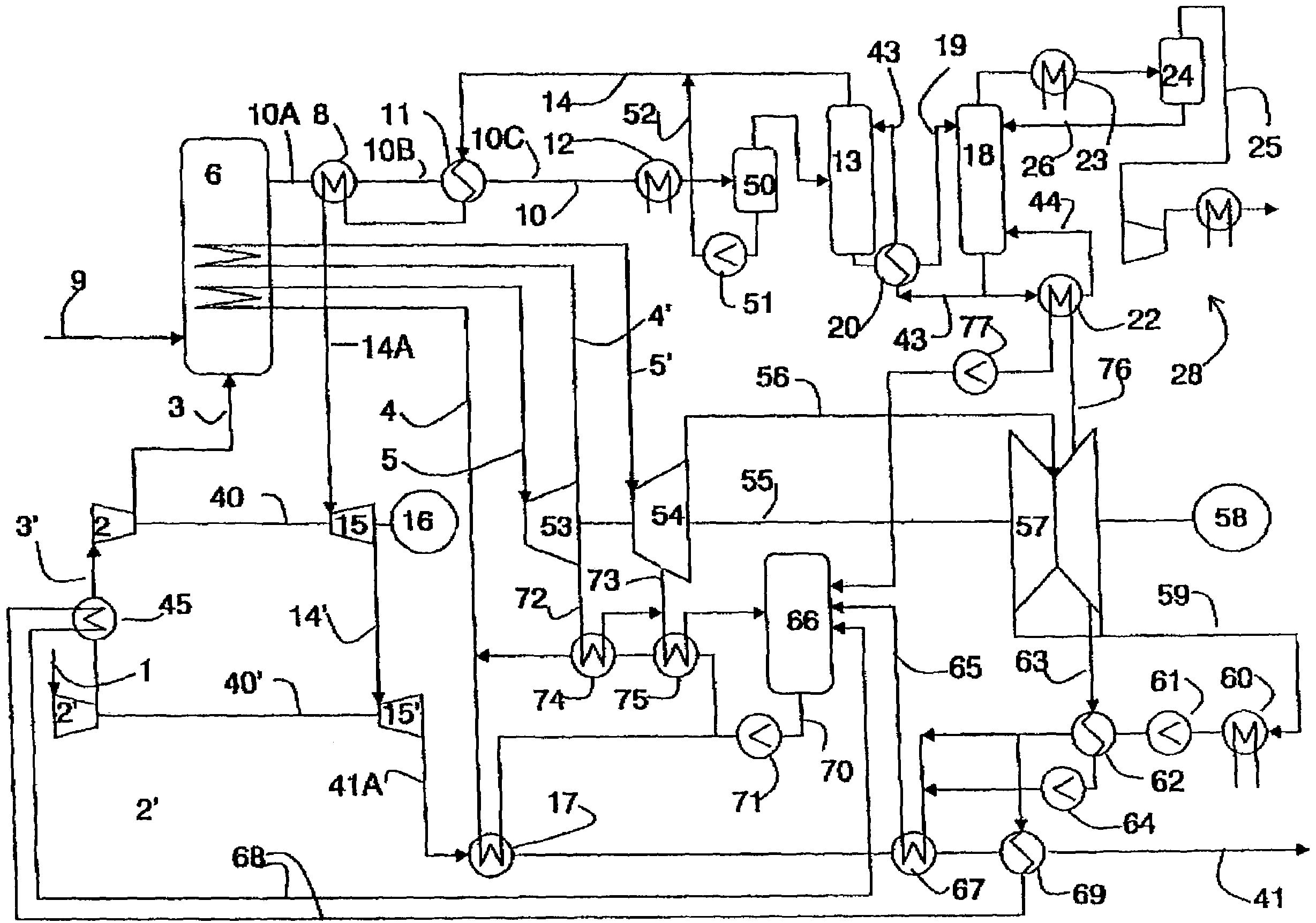
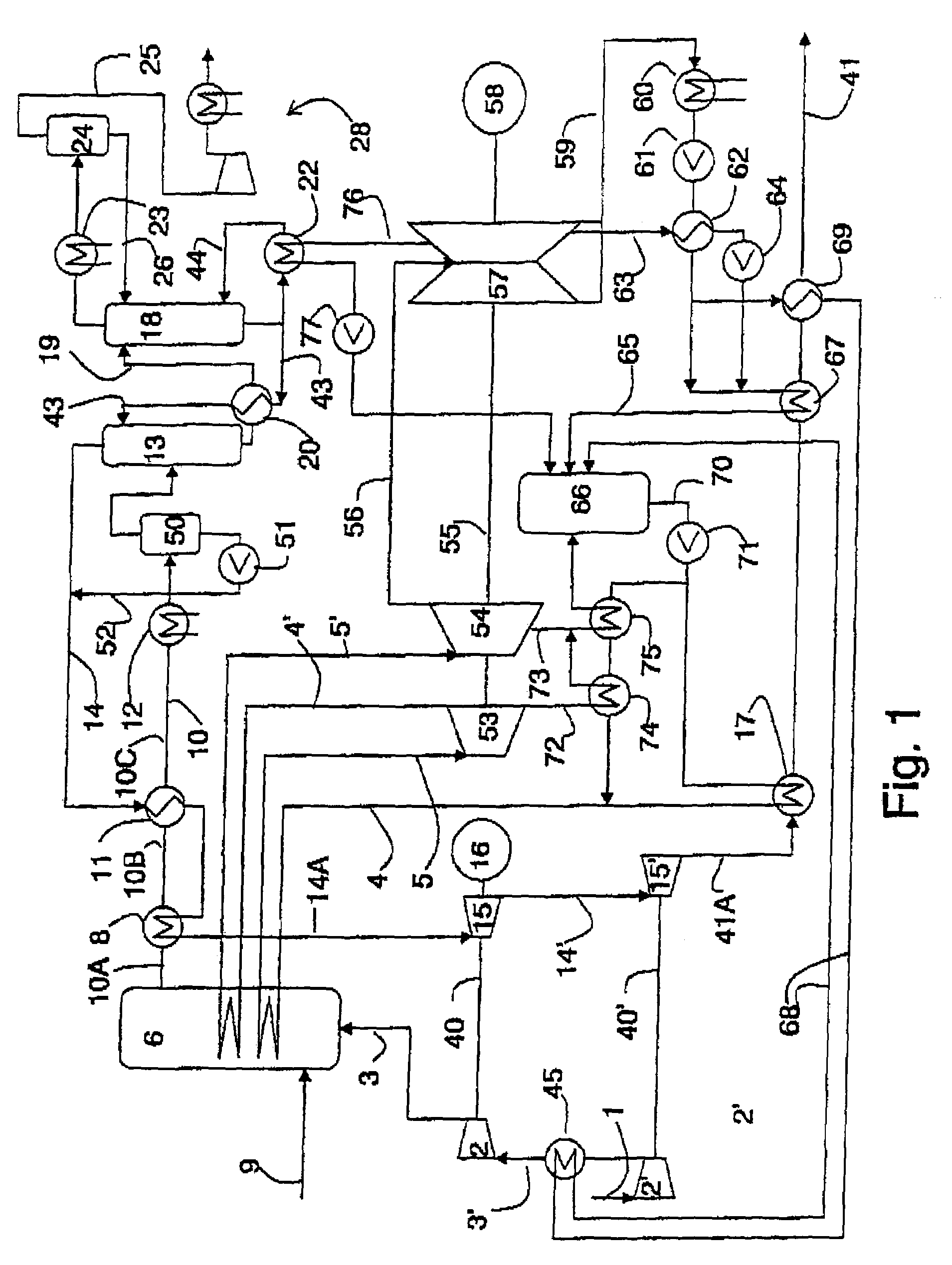
[0044]The basic configuration, as illustrated in FIG. 1, will be described first. The flow diagram is independent of the size of the plant but, with respect to the amounts described here, refers to a 400 MW plant.

[0045]The oxygen containing gas, such as air, oxygen-enriched air or oxygen, hereafter referred to in the present description and patent claims as “air”, that enters the plant in an air line 1, is compressed in a compressor 2,2′. The compressor can be in one stage, but it is preferred that the compressor 2 is two or more compressors in series, preferably with intermediate cooling of the air between the compressors 2 and 2′ as shown by a heat exchanger 45 that cools the air in line 3′ between the two compressors. Two compressors, 2,2′, as shown in FIG. 1, are preferred at the favoured working pressure for the present invention which lies around 16 bar. The incoming air is compressed in the compressor 2′ to around 4 bar. The air is led from compressor 2′ to compressor 2 by wa...


PUM


Abstract

A method for the generation of electrical power from a carbonaceous fuel, wherein the fuel is combusted in presence of oxygen under increased pressure in a combustion chamber is described. The exhaust gas from the combustion is separated into a CO2 rich fraction that is handled so that it does not escape to the surroundings, and a CO2 depleted fraction that is expanded over one or more turbines to power other processes and/or generation of electrical power, before the gas is released into the surroundings, where the temperature in the combustion chamber is reduced under the generation of steam that is expanded over steam turbines connected to electrical generator for the generation of electrical power. Additionally a thermal power plant for the performing of the method is described.

Description

BACKGROUND OF THE INVENTION[0001]1. Field of the Invention[0002]The present invention relates to a method for regulation of the CO2 content in combustion products from a pressurised, non-adiabatic combustion chamber before expansion of the products of combustion to atmospheric pressure, an installation for execution of the method and a thermal power plant where the present method is used.[0003]2. Description of Background Art[0004]The concentration of CO2 in the atmosphere has increased by nearly 30% in the last 150 years. The concentration of methane has doubled and the concentration of nitrogen oxides has increased by about 15%. This has increased the atmospheric greenhouse effect, something which has resulted in:[0005]The mean temperature near the earth's surface has increased by about 0.5° C. over the last one hundred years, with an accelerating trend in the last ten years.[0006]Over the same period rainfall has increased by about 1%[0007]The sea level has increased by 15 to 20 ...

Claims


Application Information

Patent Timeline
IPC IPC(8): F02C6/00F02C7/00B01D53/14F01K23/08F01K23/10
CPCF01K23/08F23J2215/50Y02E20/32
Inventor CHRISTENSEN, TORFLEISCHER, HENRIKBORSETH, KNUT
Owner CO2 CAPSOL
Why Eureka
Try Eureka