

Two-wheel drive two-wheeled vehicle
a two-wheel drive, two-wheel drive technology, applied in the direction of crankshaft transmission, cycle equipment, cycle, etc., can solve the problems of loss of control, unstable front wheel, vehicle damage, etc., to minimize the effect of torque, reduce the risk of riding, and increase the strength of the system
- Summary
- Abstract
- Description
- Claims
- Application Information
AI Technical Summary
Benefits of technology
Problems solved by technology
Method used
Image

Examples
first embodiment
of the Invention Illustrating a Two-Wheel Drive Motorcycle with a Drive System Originating from the Engine and Transmission
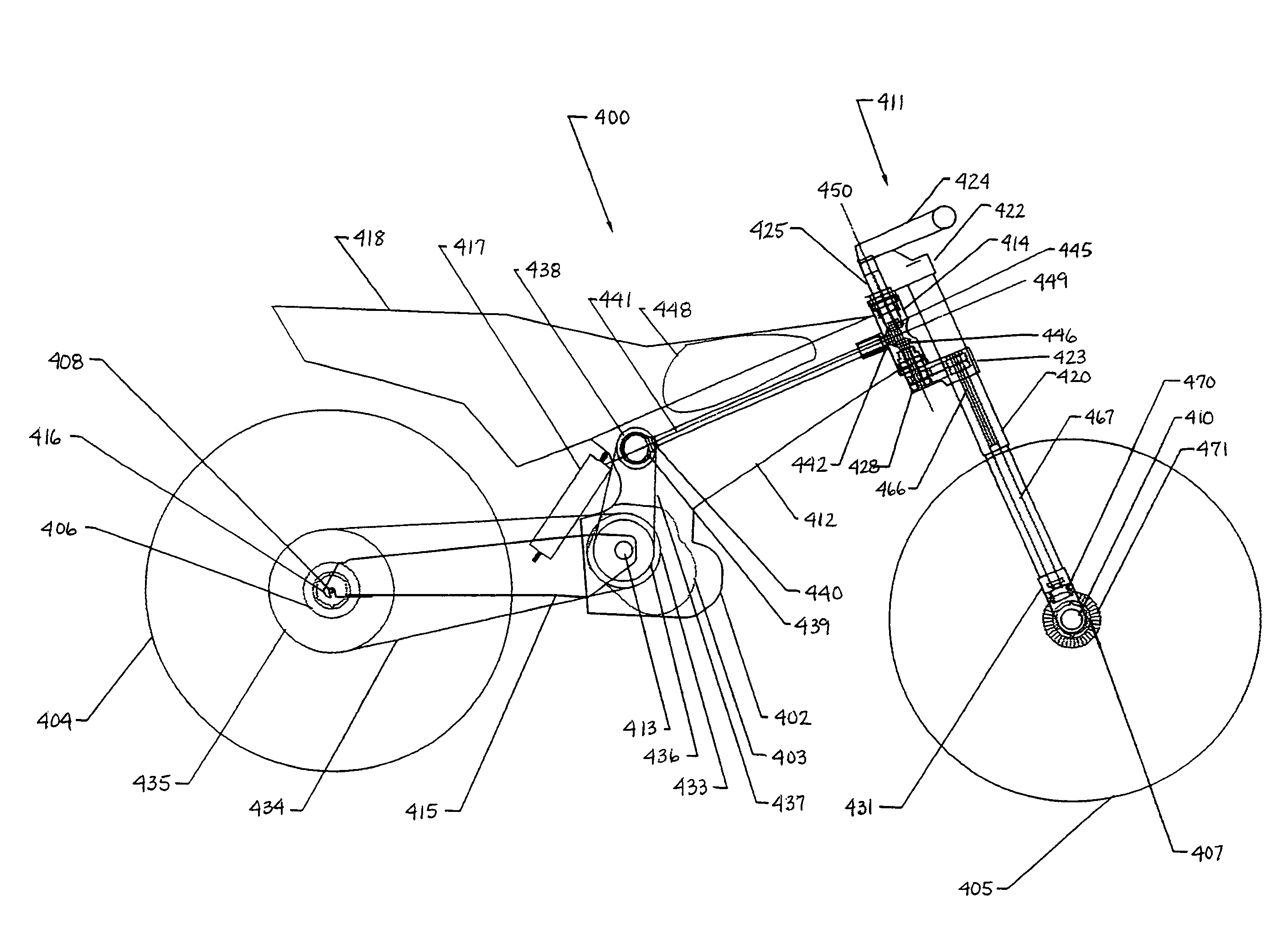
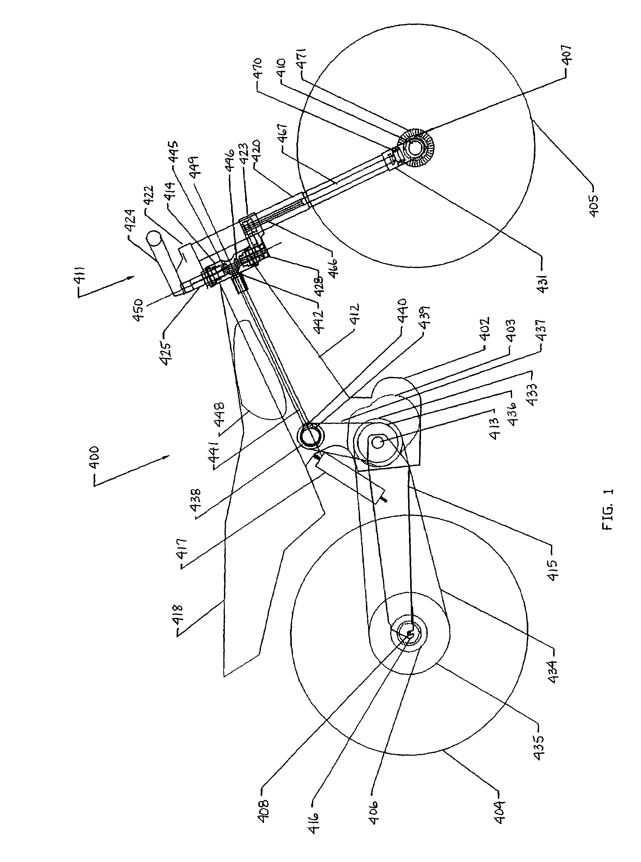
[0079]FIG. 1 is a side view of the first embodiment of the invention illustrating a two-wheel drive motorcycle 400 with a motorcycle front wheel drive 401 (see FIG. 6) originating directly from an engine 402 and motorcycle transmission 403. FIG. 6 is a side view of the rear wheel and front wheel drive system of a two-wheel drive motorcycle according to the present invention. The two-wheel drive motorcycle 400 of the present embodiment includes a rear wheel 404 and a front wheel 405. The rear wheel 404 further includes a rear wheel hub 406 and the front wheel further includes a one-way front wheel hub 407. The rear wheel 404 and rear wheel hub 406 rotate about a rear wheel axle 408 that is attached to a motorcycle frame. The front wheel 405 rotates about a front wheel axle 410 that is attached to a motorcycle steering mechanism 411 of the two-wheel drive motorcyc...
second embodiment
of the Invention Illustrating a One-Way Front Hub with Roller Clutch for a Two-Wheel Drive Motorcycle
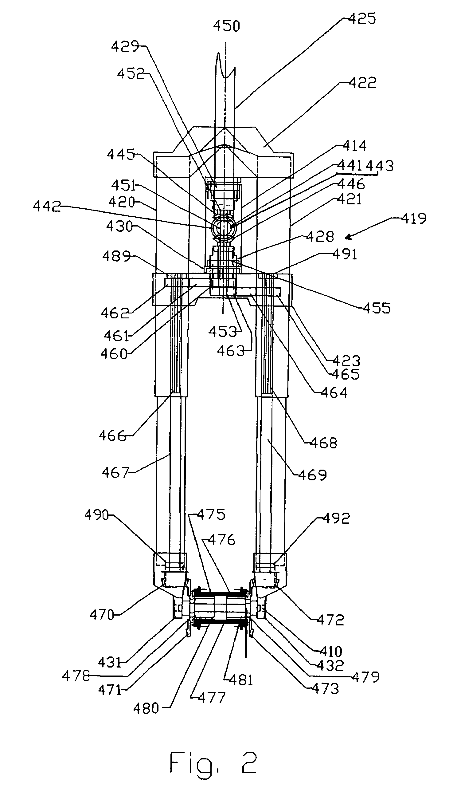
[0104]FIG. 5 is a front view of a one-way front wheel hub 407 for a two-wheel drive motorcycle 400 with a right roller clutch 475 and a left roller clutch 476. In the present embodiment, the one-way front wheel hub 407 includes a motorcycle outer hub shell 477, a right inner hub shell 478 and a left inner hub shell 479. The right inner hub shell 478 further includes a right roller clutch surface 480 and the left inner hub shell 479 further includes a left front roller clutch surface 481. In the present embodiment, the right inner hub shell 478 and left inner hub shell 479 are separate pieces to enable easy assembly, however, they could also be a single piece. Alternatively, the right inner hub shell 479 and left inner hub shell 480 could each be made of several pieces in order to accommodate a motorcycle torque-limiting clutch configuration (not shown) similar to the torque-limiting ...
third embodiment
of the Two-Wheel Drive Vehicle Illustrating a One-Way Front Hub with Roller Clutch and Torque Limiting Clutch
[0111]FIG. 7 is a front view of a one-way front hub 213 for a two-wheel drive vehicle with a front roller clutch 214. In the present embodiment, the one-way front hub 213 includes an outer front hub shell 215 and an inner front hub shell 216. The inner front hub shell 216 further includes a front hub roller clutch surface 217. In the present embodiment, the inner front hub shell 216 and front hub roller clutch surface 217 are separate pieces to accommodate a torque limiting clutch assembly 299 discussed below and the inner front hub shell 216 further includes an inner hub spring shaft 312. However, the inner front hub shell 216 with front hub roller clutch surface 217 could also be a single piece in configurations without a torque-limiting clutch assembly 299.
[0112]A front axle 59 rotationally attaches within the inner hub shell 216 and is supported via a first front hub axle...
PUM
 Abstract
Description
Claims
Application Information