Magnetic compass structure

a magnetic compass and structure technology, applied in the direction of instruments, surveying and navigation, measurement devices, etc., can solve the problems of inability to make instruments, inconvenient construction, and lack of accuracy of prior instruments, and achieve the effect of easy production, high accuracy, and easy correction for declination

Inactive Publication Date: 2008-02-19
BELEW SAMUEL B
View PDF12 Cites 3 Cited by
  • Summary
  • Abstract
  • Description
  • Claims
  • Application Information

AI Technical Summary

Problems solved by technology

However, these prior instruments lack accuracy because it is not possible to see the bearing information, both far and close, practically simultaneously without moving the head or unit and thus the body, and without refocusing of the viewers eye lens.
These instruments are complicated to construct and / or they block the viewing of the far target.
Since it is essential that any magnetic disk type compass be held at a level position, having a part of the distance viewing blocked and not being able to tilt the compass to compensate can make it unusable in a field situation.
Nor is there such an instrument that allow declination correction with accuracy and ease and an instrument with so few parts.
Nor is there an instrument that can give accurate readings with such an ease of use and that can be as compactly constructed and at such a light weight for use by backpackers or others where weight is a big consideration.

Method used


Image

  • Magnetic compass structure
  • Magnetic compass structure
  • Magnetic compass structure

Examples


Embodiment Construction

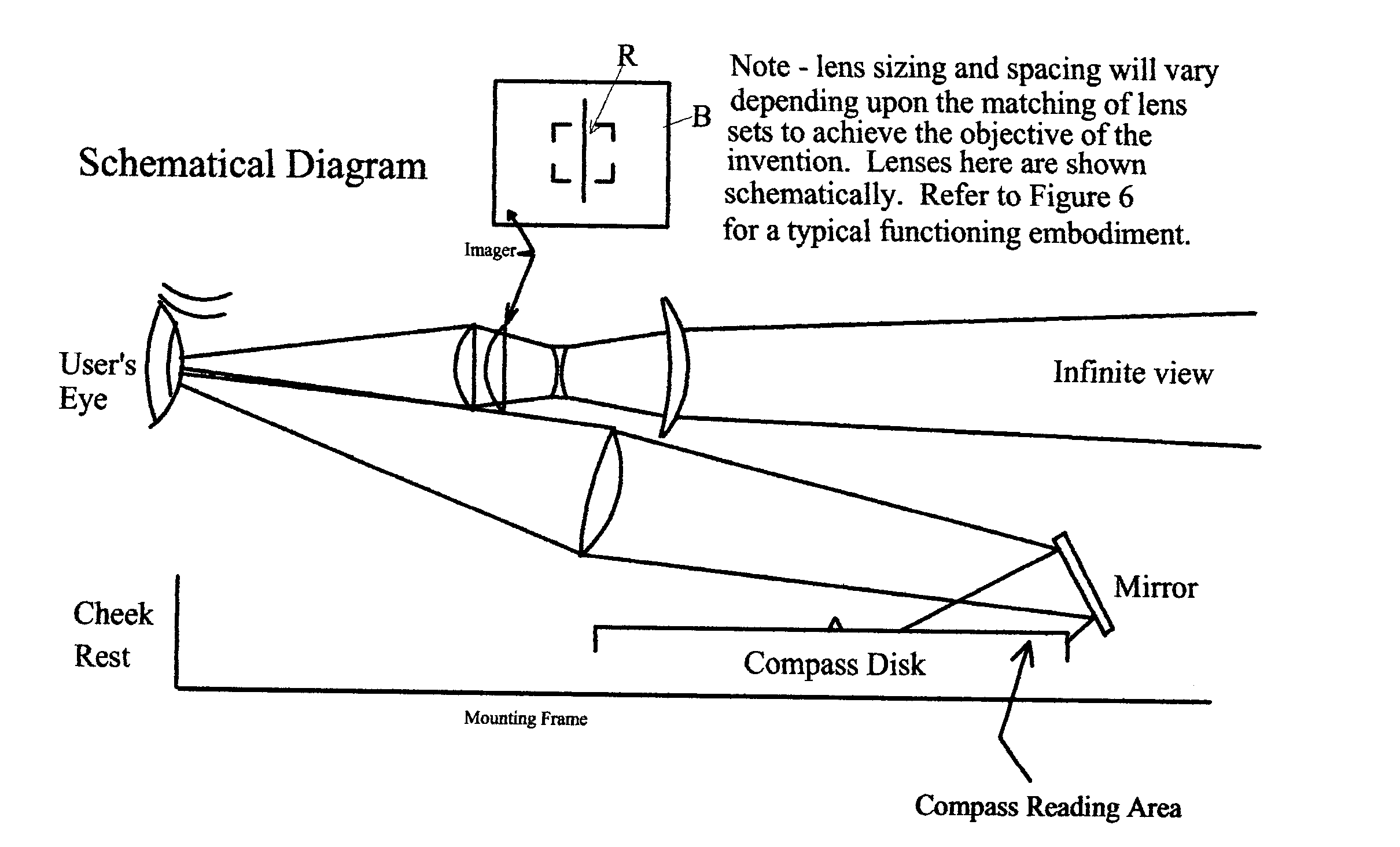
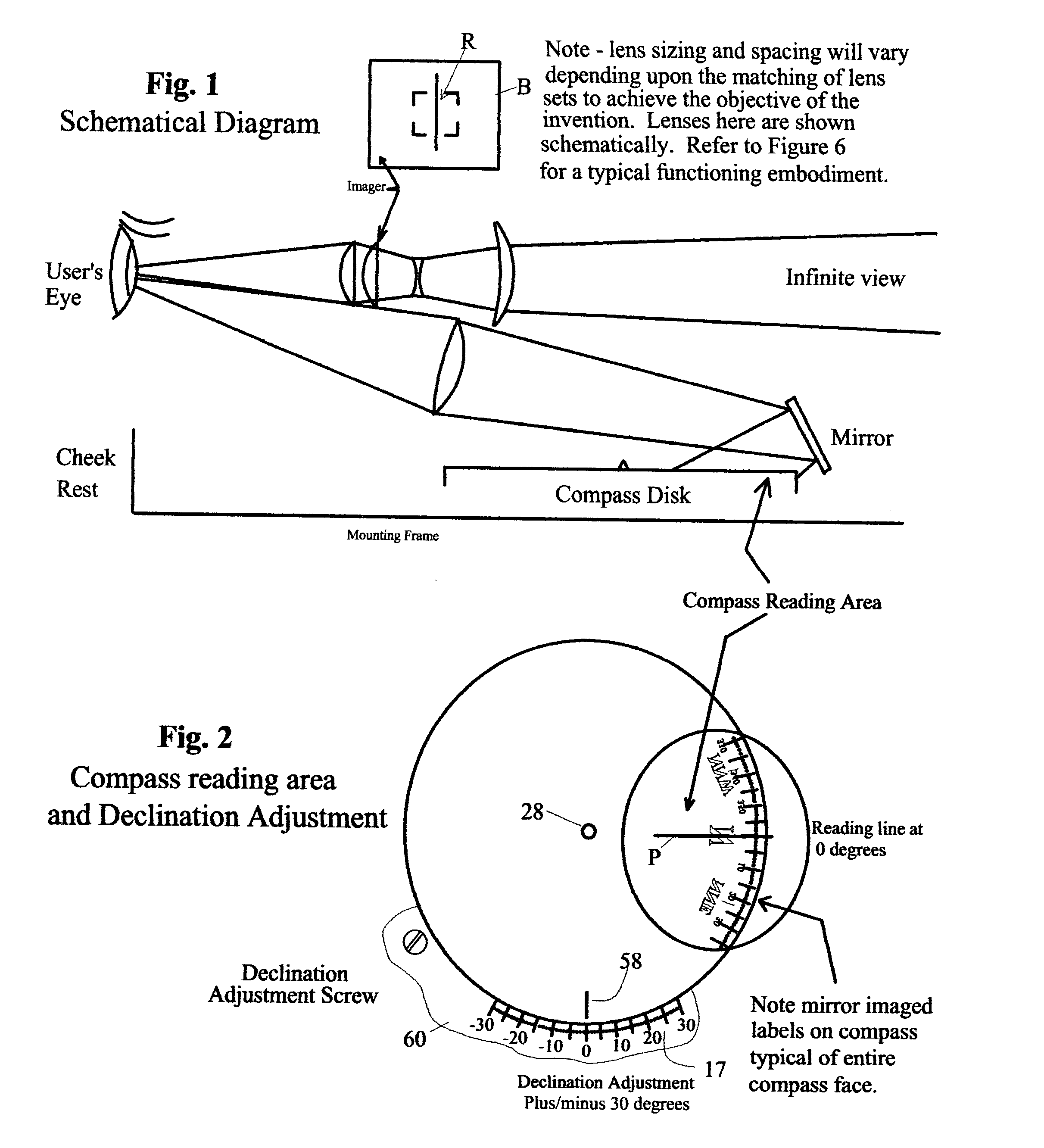
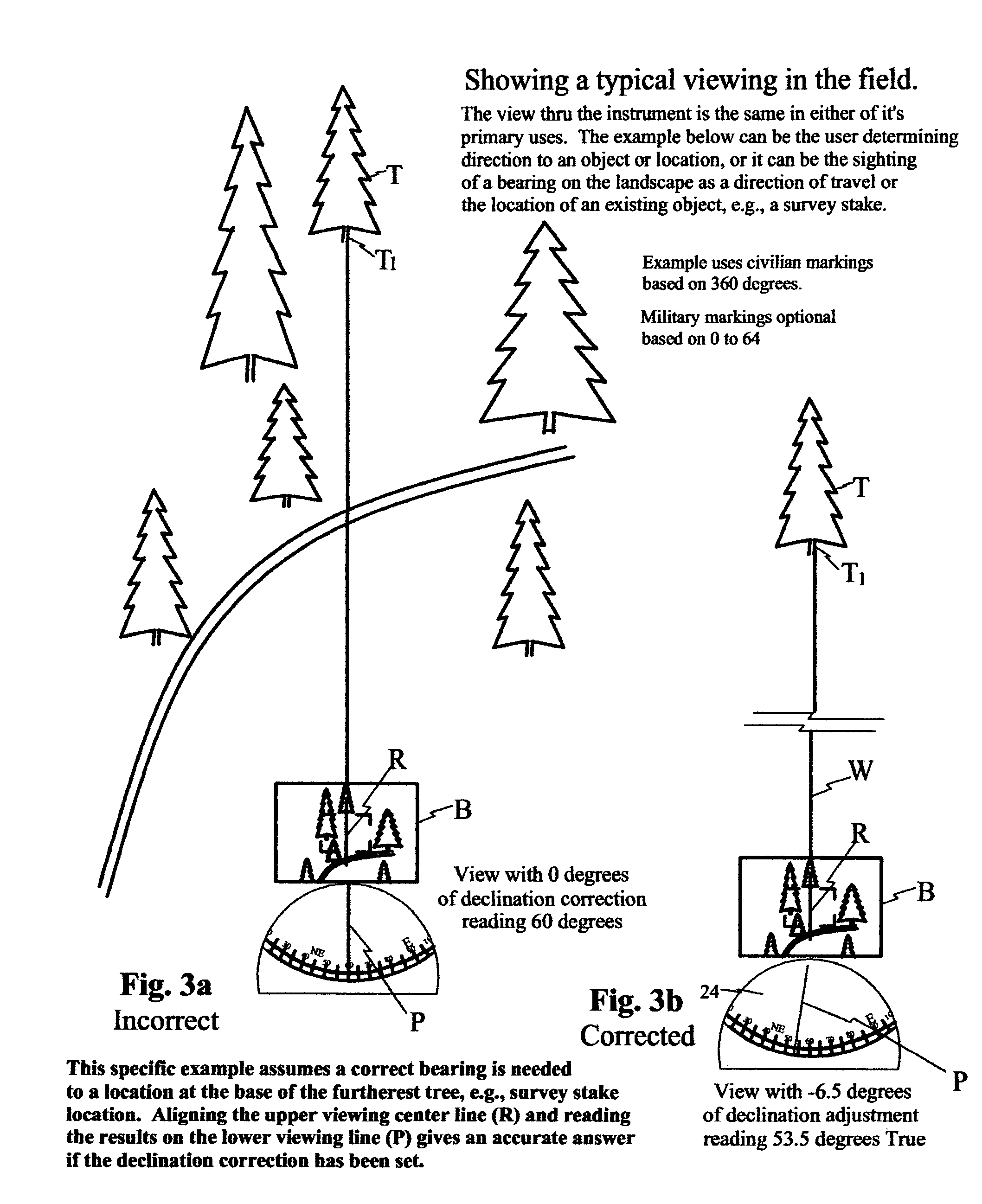
[0025]Using a conventional disk magnetic compass or an equivalent of the same, two separate imaging systems allow focusing on (1) the target object or spot in the distance, and (2) the compass bearing of the hand held instrument. For the first objective four lenses and a vertical marker allow a corrected distant view. For the second objective a magnifying lens and small mirror allows a detailed viewing of a compass readout, with a movable reading mark correctable for declination. When declination exceeds twenty degrees at a location then a manufacturing modification is made to allow accurate adjustment for a specified area.

[0026]FIG. 1 is a basic schematic diagram of a typical embodiment of the invention. With the eye at the established location, two sets of optics allow the viewing of either set of information from the same location. In this embodiment, for the far view lens elements (A-D) allows the far view to be observed with the eye focused or adjusted for nearsighted viewing. ...


PUM


Abstract

A simple self-contained, hand-held instrument for reading an azimuth or bearing in relation to the earth's magnetic field either out in the field or on the water with substantial accuracy. Means are provided that places the far object into the same focal plane (or focal point) as the close up bearings on the compass disc face, thus allowing the eye to instantly see both images without adjustment between near-sight and far-sight. Means are also provided for the adjustment of the instrument for the local variation or declination of the earth's magnetic field versus that of true north.

Description

[0001]This application claims priority under 35 U.S.C. 119(e)(1) based on Applicants Provisional U.S. Patent Application Ser. No. 60 / 665,686 filed Mar. 28, 2005 and titled “HANDHELD OPTICAL MAGNETIC EARTH FIELD BASED BEARING DETERMINING INSTRUMENT”.BACKGROUND OF THE INVENTION[0002]1. Field[0003]The invention lies in the field of orienteering, positioning and surveying instruments in general. More specifically, it refers to compass structure that allows a specific compass bearing to be identified with great accuracy, even for one with poor eyesight. More specifically the invention features a small handheld self-contained compass structure having a distant object viewing system and a compass face indicia viewing system, wherein the lines of sight of the two systems (lens sets) are in general alignment and wherein the focal points (on the viewers eye) for both systems are substantially coextensive, and whereby extremely rapid eye sighting from one line of sight to the other will not re...

Claims


Application Information

Patent Timeline
Patent Type & Authority Patents(United States)
IPC IPC(8): G01C17/00
CPCG01C17/20
Inventor BELEW, SAMUEL B.
Owner BELEW SAMUEL B
Why Eureka
Try Eureka