[0013]Solutions are known in which the released
hydraulic fluid exits the connection on the side or through the interior of the valve housing. The invention however considers it useful to design the outlet bores in the connection parallel to the
blind hole in order to be able to specify an optimally short path for the
hydraulic fluid. The hydraulic fluid is already uncovered by the seal when passing over the radial bores so that the hydraulic fluid can then be drained quickly through the outlet bores. In this it has proven especially useful to provide bores in the wall of the valve housing in addition to the outlet bores in the connection, or to use only the bores in the valve housing as outlet bores. Already the description clarifies that the hydraulic fluid can be drained, and hence the pressure in the
system can be decreased, via the shortest possible path. Because here large amounts of hydraulic fluid have to be removed with the described valve in a short time, the design of bores and outlet bores will surely be the preferred one.
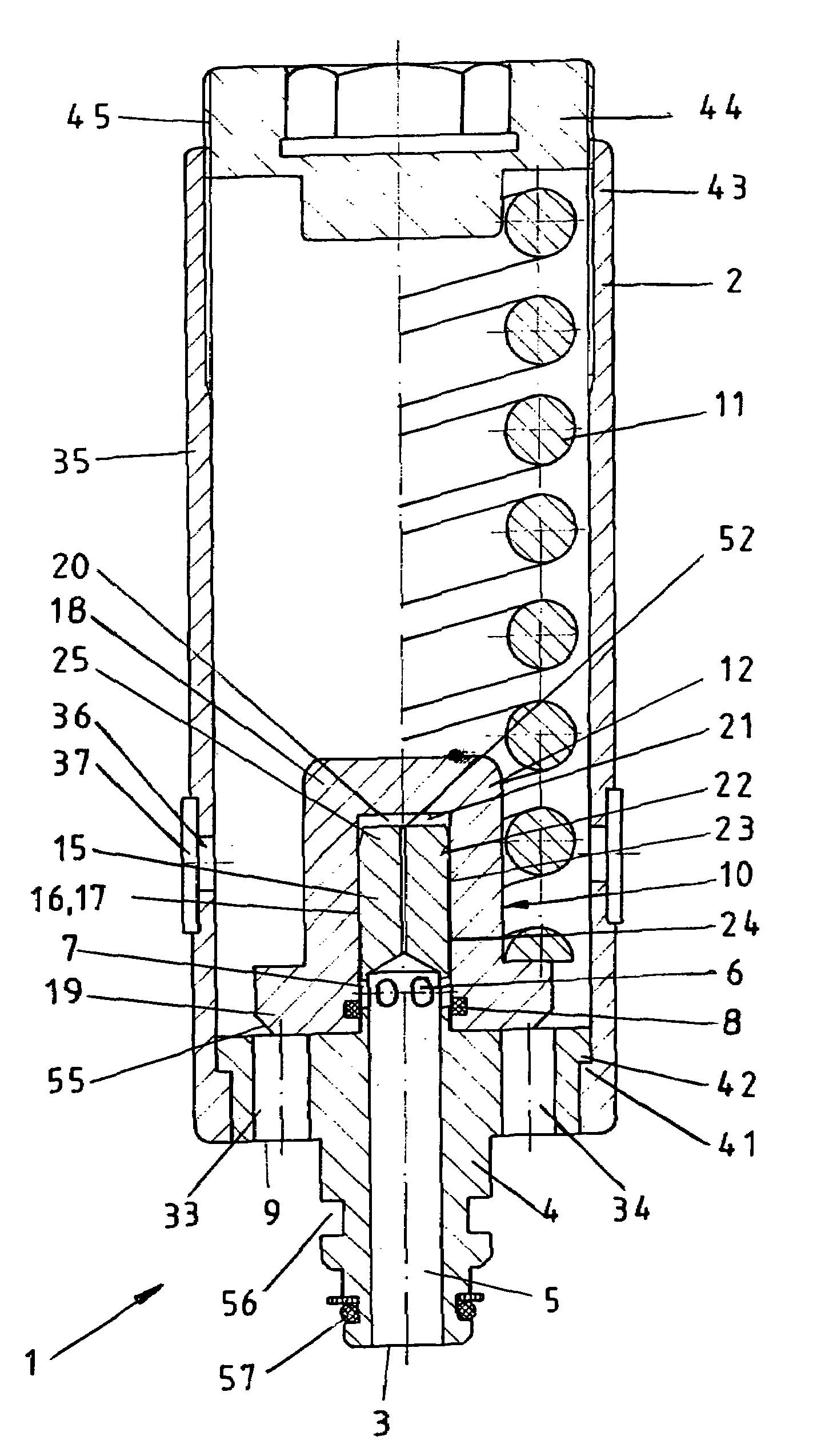
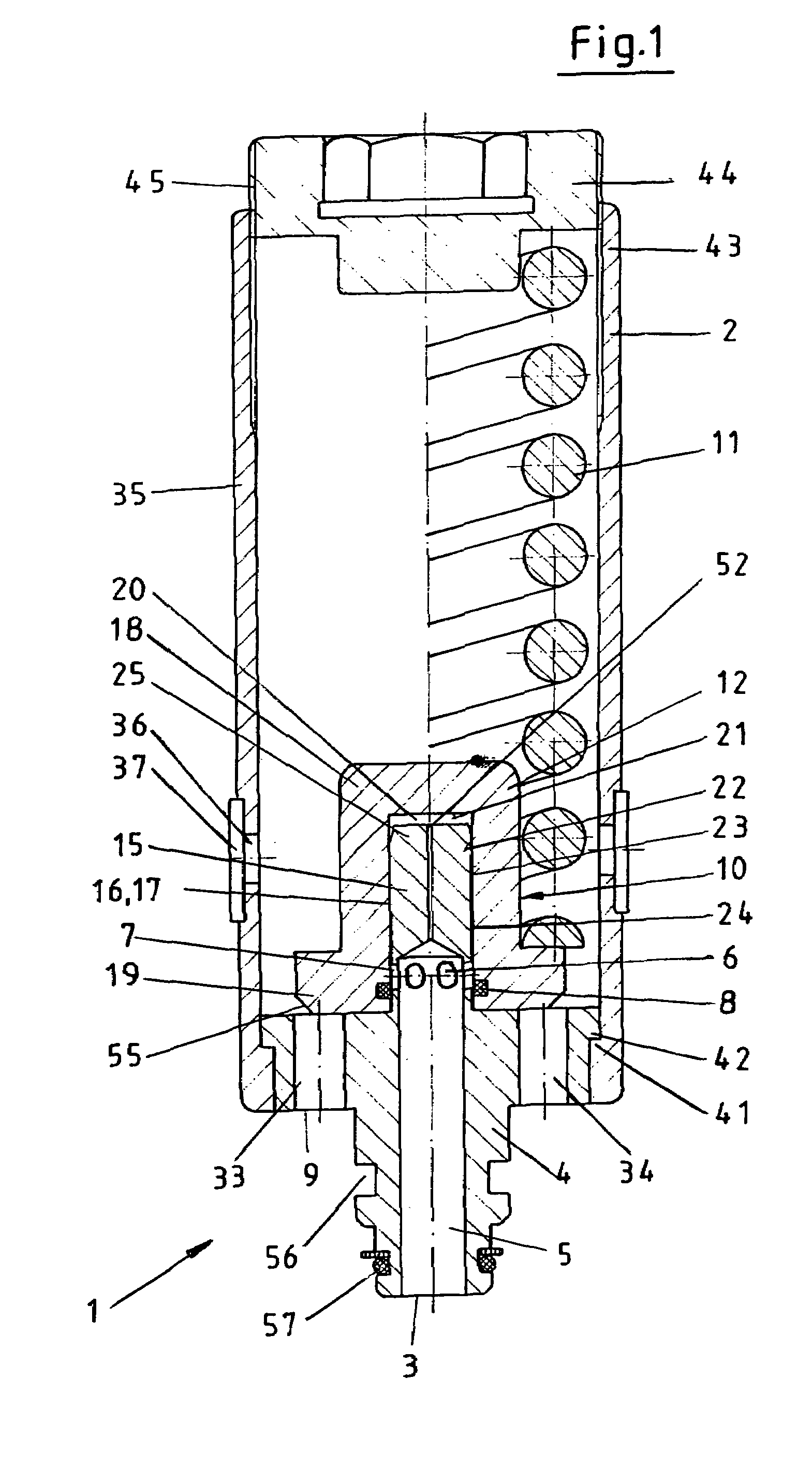
[0014]One embodiment of the invention that is beneficial in terms of its complexity provides that the blind hole is designed as a through-hole that continues up to the
piston end, so that the hydraulic fluid can always be applied to the valve spring
retainer, allowing it to be lifted quickly when an overload occurs. The
system pressure hence acts fully upon the valve spring retainer so that said retainer lifts especially quickly and opens up the path to the outlet bores for the hydraulic fluid. Despite this design a kind of pressure chamber remains, even though it will empty partially when the pressure relief valve is closed again.
[0015]The design of the entire pressure relief valve is further simplified by equipping the valve housing on the nipple-side with a retaining projection, which is designed such that it pushes a corresponding lug on the connection from behind, and by arranging a rotatable spring adjusting screw on the opposite end of the valve housing. During
assembly the valve housing is pushed from the connection side over said connection, then the valve spring that rests on the movable valve spring retainer is introduced, whereupon the valve spring and hence the remaining parts are evenly tightened with the spring adjusting screw. The spring adjusting screw can then also simultaneously be used to adjust the valve.
[0009]A particularly useful embodiment of the afore-mentioned piston is one in which the piston is part of the connection. The piston and connection hence form a unit, wherein the piston projects accordingly far beyond the connection base so that the cylindrical head section of the valve retainer can safely frame it.
[0017]Due to the special circumstances in
hard coal mining, the
diameter of the props used becomes increasingly larger, especially in shield construction, so that the quantity of hydraulic fluid that needs to be drained constantly increases as well. The present invention further addresses these particular problems in that the blind hole in the connection has a
diameter of 10 mm or more, so that hydraulic props having a piston
diameter of 360 mm or more can be protected effectively via the pressure relief valves. Overall 800 l hydraulic fluid per minute can be removed, which enables a timely and prompt relief for such hydraulic assemblies.
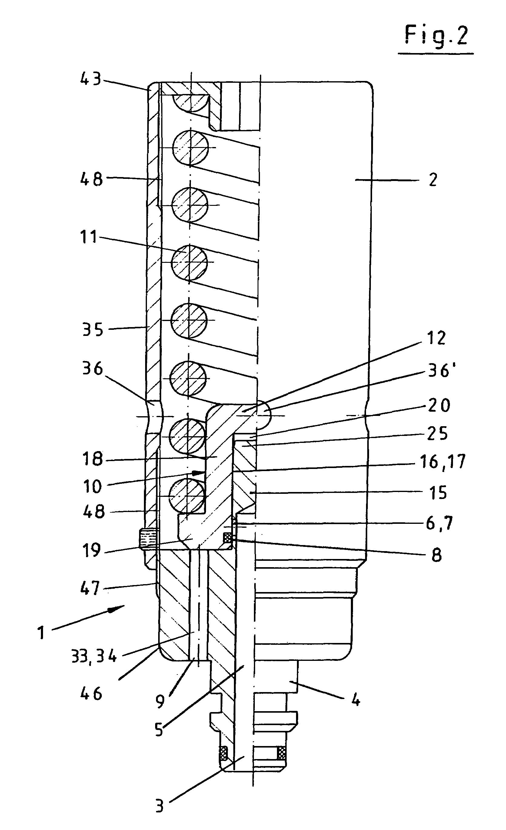
[0019]An especially effective and safely operating design of a damping chamber is provided pursuant to the invention and implemented in that the damping chamber, which is formed between the connection that contains a blind hole and radial bores and the displaceable closing part, is designed such that it has a direct connection with the blind hole and hence with the
system pressure. In this way it is ensured that independent from the installation situation of the pressure relief valve, there is always a guarantee that the damping chamber is filled with hydraulic fluid already at the start of the opening process, in particular with the
system pressure, so that no air bubbles or other impairments can develop. In this manner the valve is advantageously prevented from destroying itself hydraulically, so that not only can a longer service life can be achieved, but above all a fully effective and damped pressure relief valve is available at all times.
[0020]Furthermore it is beneficial and useful if the damping chamber is connected to the blind hole via a throttling port so that, when closing the pressure relief valve again and hence when the valve spring returns into its starting position, throttling is guaranteed, which in the end is dependent upon the diameter of the throttling port. This way specific damping can be achieved without requiring further controls and adjustments.
[0021]The availability of a correspondingly filled damping chamber and hence of a permanently active and ready-to-use pressure relief valve is achieved in particular in that the closing part is formed by a piston that represents a portion of the connection and a head section of the valve spring retainer, said section comprising the piston and taking on a correspondingly cylindrical design, wherein the throttling port is arranged in the piston and connects the deepest inside of the cylindrical valve retainer to the blind hole. Thus, during use of the pressure relief valve, the system pressure can always be applied to the damping chamber via the throttling port, or the damping chamber is always filled with accordingly pressurized hydraulic fluid. If then the situation arises in which the pressure relief valve opens due to an overload situation, further filling occurs via the throttling port, at least until the radial bores are completely clear and the hydraulic fluid can flow past the valve spring retainer to the outlet bores or holes. When closing the pressure relief valve again, the afore-mentioned throttling develops because the spring must first push the hydraulic fluid out of the damping chamber before the valve spring displaces the valve spring retainer accordingly.
[0022]Further above it was pointed out that the piston and the valve spring retainer comprise suitable smooth contact surfaces. Since the arrangement of the tightening seal and / or of the corresponding sealing ring is provided beneath the radial bores, the hydraulic fluid can also enter the space between the piston and valve spring retainer via the radial bores. A safe filling of the damping chamber is supported, however, by the fact that between the outer wall of the piston, between the radial bores and the piston tip, and the inner wall of the cylindrical head section another supply opening is incorporated for the direct supply of the damping chamber. Already the choice of words clarifies that this path also represents a direct connection between the damping chamber and the blind hole so that this path also offers the system pressure the possibility of applying an even effect on the damping chamber.
[0023]The
insertion of the piston into the cylindrical head section of the valve spring retainer is facilitated in that the piston tip has a slightly tapered design so that no jamming can occur when inserting it into the corresponding opening of the head section.
[0024]A certain minimum size or starting size of the damping chamber is provided and adjusted in that the piston tip is designed to maintain a
minimum distance to the deepest inside of the cylindrical head section, thus specifying the starting size of the damping chamber. This in turn forms a buffer again, which prevents contact of the individual parts because a certain buffer of hydraulic fluid is maintained at all times. Apart from this, the described supply paths always guarantee direct contact between the damping chamber and the hydraulic system fluid.
[0025]The even upward motion of the cylindrical head section of the valve spring retainer is purposefully supported pursuant to one embodiment in that the base of the valve retainer comprises a chamfer on the outer edge, while it is even in the remaining areas and ensures that the valve spring retainer rests securely on the connection. As soon as with this embodiment the hydraulic fluid has passed the radial bores and the first upward motion of the valve spring retainer has been reached, the hydraulic fluid draining through the tight gap pushes the valve spring retainer up, in particular due to the fact that an upward motion is specified and / or supported through the chamber.
[0026]The invention is characterized especially in that a simple and safely operating pressure relief valve is created, which involves direct hydraulic damping and which operates with only few
moving parts. This reduction in
moving parts alone leads to an improved response accuracy and hence an improved functioning of the pressure relief valve. Also the manufacture is facilitated because the connection can be equipped with a continuous axial bore or a blind hole, which no longer contains
moving parts. Rather the piston, or better the piston part of the connection itself or of a corresponding partial region on which the correspondingly designed valve spring retainer can move, [is designed such] that it can prestress the spring accordingly, driven by the hydraulic fluid, and can connect the inlet side with the outlet side so that the hydraulic fluid peak can be reduced. Everything takes place evenly and quickly so that even with the specified dimensions large amounts, i.e. 800 l per minute or more, can be removed, thus preventing the damaging overload from having an unfavorable effect on the allocated hydraulic
assembly. When closing the pressure relief valve again, the movement is controlled by the arrangement and configuration of the damping chamber such that no wobbling of the valve can arise, but rather an even detensing of the valve spring occurs, and hence a smooth, even and secure closing of the pressure relief valve.

