Subsea lubricator device and methods of circulating fluids in a subsea lubricator

Inactive Publication Date: 2008-02-19
FMC KONGSBERG SUS
View PDF15 Cites 31 Cited by
  • Summary
  • Abstract
  • Description
  • Claims
  • Application Information

AI Technical Summary

Benefits of technology

[0019]An important aspect of the invention is to avoid formation of hydrates caused by water contacting hydrocarbones.
[0020]This is obtained by a lubricator comprising at least one bypass, whereby fluids may be circulat

Problems solved by technology

Such a lubricator may not be used for circulation in the well.
Another disadvantage is the practical problems of being able to circulate out unwanted fluids entering the lubricator.
Hydrocarbons, or other contaminating fluids entering the lubricator during

Method used


Image

  • Subsea lubricator device and methods of circulating fluids in a subsea lubricator
  • Subsea lubricator device and methods of circulating fluids in a subsea lubricator
  • Subsea lubricator device and methods of circulating fluids in a subsea lubricator

Examples


second embodiment

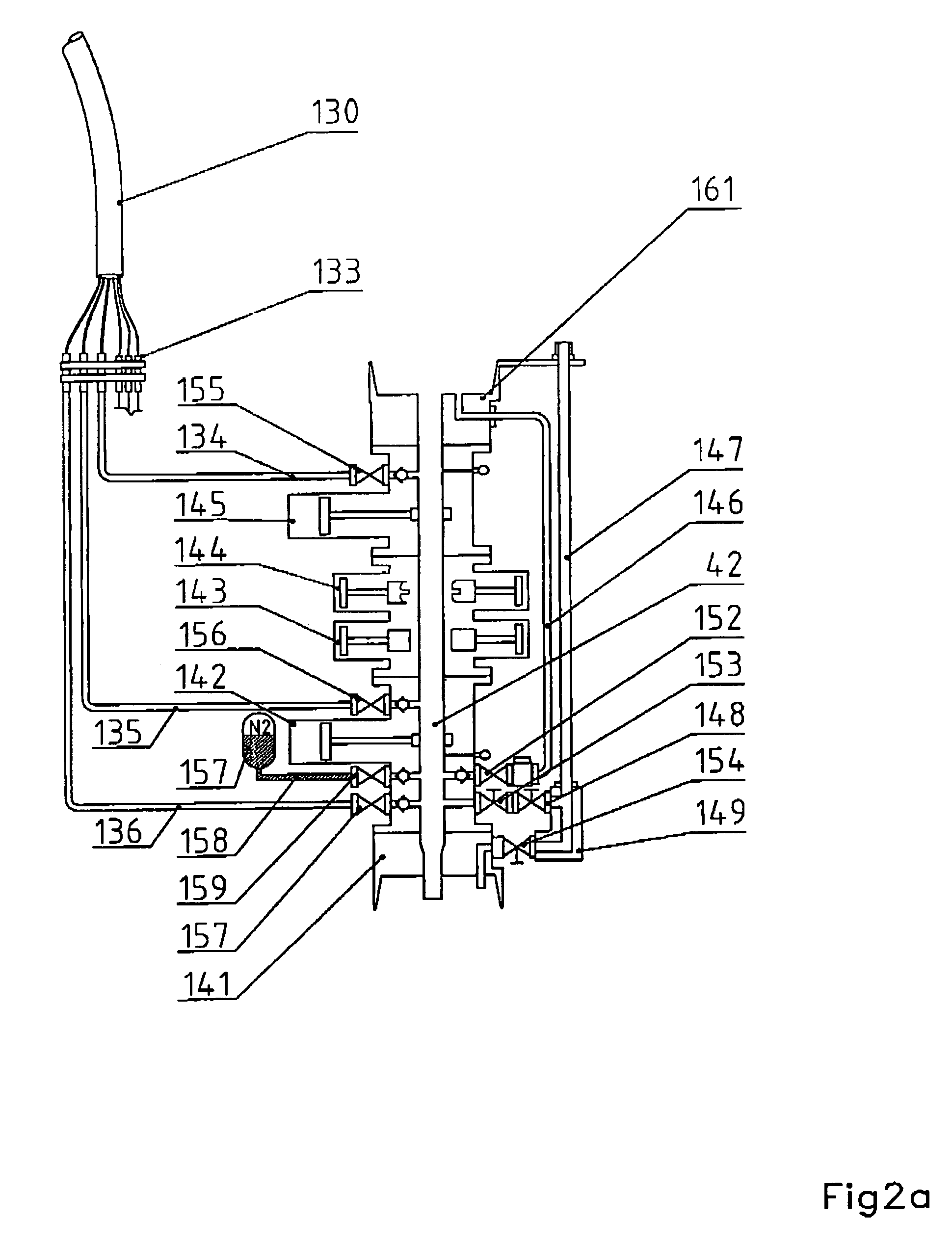
[0080]Now, it shall be referred to FIG. 2 showing the invention. FIG. 2a shows the lower part of the lubricator (the pressure control assembly) and FIG. 2b shows the upper part with the tool housing.

[0081]A pressure control assembly 140 comprises a lower connector 141 for attachment to a Christmas tree, and an upper connector 161 for attachment to a corresponding connector at the tool housing assembly (FIG. 2a). The assembly consists of the following valves, mentioned from below: a lower blind ram (gate valve) 142, a pipe ram 143, a shear ram 144, and a upper stop valve 145

[0082]A passage 42 extends axially in the pressure control device in the same manner as discussed above

[0083]A first bypass 146 is arranged in a manner providing a fluid passage around the valves mentioned above. In FIG. 2a the bypass is shown as a pipe being connected to the connector 161 at its upper end, and communicating with the passage 42 of the LIP-assembly via a passage at its lower end. A stop valve is lo...

third embodiment

[0127]In a third embodiment the apparatus may be used to shut down the well by insertion of plugs into the plug profiles in the tubing hanger either in the main passage 19, or in the lateral passage (the annulus passage) 29. During insertion of a plug into the profile an adapter of the kind discussed above (FIG. 3) is used, the passages 42, 62 of the lubricator being in line with the main passage 12 of the Christmas tree. A running tool is used to run, and to locate, or in turn to retrieve the plug. Circulating out fluids is done in the same manner as discussed previously.

[0128]However, when inserting a plug into the profile 29 the main passage 42 has to be brought into axial extension with the annulus passage 22 of the Christmas tree. Another adapter 190 is connected to the LIP-assembly, as shown in FIG. 6. This is designed such that, during attachment of the lubricator to the Christmas tree, the passage 42 of the LIP-assembly extends axially in the extension of the passage in the ...


PUM


Abstract

Subsea lubricator device, comprising a blowout preventer assembly, a tool housing assembly and a stuffing box, intended to be located at a subsea Christmas tree, and methods of circulating fluids in a subsea lubricator. The device comprises a blowout preventer (40) and a lubricator (60). Along the entire length of the device a bypass (46, 66) is located. The bypass communicates fluid with the device via a fluid connection (72) at the upper end of the tool housing and via a valve assembly (51) at the bottom of the blowout preventer. This permits removal of gas or oil being present in the device by circulating the hydrocarbons in the well.

Description

CROSS-REFERENCE TO RELATED APPLICATION[0001]This application claims priority of International application number PCT / NO00 / 00318, filed Sep. 28, 2000, which in turn claims priority of Norwegian application number 19994784, filed Oct. 1, 1999.FIELD OF THE INVENTION[0002]The invention relates to a subsea lubricator device, comprising a blowout preventer assembly, a tool housing assembly and a stuffing box, intended to be located at a subsea Christmas tree.[0003]Moreover, the invention relates to methods of circulating fluids in a subsea lubricator.BACKGROUND OF THE INVENTION[0004]Works are performed in an oil or gas well, among others, to stimulate or treat the well to increase production, to replace various equipment such as valves, to make measurements, to monitor the state of the well, or anything else being required.[0005]Treatment of the well, for increasing the production rate or volume, is made after a cost / benefit evaluation. Even if the production from a well may be increased ...

Claims


Application Information

Patent Timeline
IPC IPC(8): E21B29/12E21B33/076
CPCE21B33/072
Inventor HOEL, KARL-WILLIE
Owner FMC KONGSBERG SUS
Why Eureka
Try Eureka