Brake disc for automotive disc brake assembly

a technology for brake discs and brake assemblies, applied in the field of brake discs, can solve the problems of insufficient effectiveness of grooves, reduced capacity and heat dissipation, and thermal deformation of brake discs b>50/b>, so as to prevent brake noise and suppress thermal deformation

Inactive Publication Date: 2008-02-19
KAWASAKI MOTORS LTD
View PDF22 Cites 15 Cited by
  • Summary
  • Abstract
  • Description
  • Claims
  • Application Information

AI Technical Summary

Benefits of technology

[0009]The present invention has been devised in view of the foregoing situations and is intended to provide a brake disc in a disc brake for a vehicle, which can be manufactured lightweight, suppress the thermal deformation and is effective to prevent brake noises.
[0011]With the brake disc of the structure described above, not only can the weight be reduced in a quantity corresponding to the outer recesses, but also an outer peripheral portion of the brake disc, which has a greater thermal deformation than the inner peripheral portion because of the diameter greater than that of the inner peripheral portion, can expand along the outer recesses in the circumferential direction and, therefore, the thermal expansion of the outer peripheral portion can be sufficiently allowed not only in the circumferential direction, but also in the radial direction. In other words, the thermal deformation of the outer peripheral portion can easily be accommodated and an undesirable deformation of the brake disc in a direction across the thickness thereof (i.e., the axial direction) can be suppressed. Also, since the radial width of the braking surfaces changes in the circumferential direction of the brake disc, the surface area of each of the braking surfaces in contact with the frictional pads varies as the brake disc rotates and, therefore, resonance which would occur between the brake disc and the frictional pads can advantageously be prevented to thereby minimize the phenomenon of brake noises resulting from the resonance during braking.
[0012]The number of the outer recesses is preferably equal to or greater than that of the support members. According to this structural feature, because the number of the outer recesses in a number equal to or greater than that of locations at which the brake disc are fastened by the support members, the thermal deformation of the outer peripheral portion can easily be accommodated in the outer recesses.
[0014]Preferably, each of the outer recesses has a depth that is set to a value within the range of 0.15 to 0.25 times a maximum width of the braking surface delimited between outermost and innermost peripheral edges of the braking surface. If the depth of each outer recess is smaller than the value 0.15 times the maximum width of the braking surface, the degree of change of the radial width of the braking surface in the circumferential direction becomes too small and, therefore, respective effects of the present invention to reduce the weight, suppress the thermal deformation and prevent the brake noises would be minimal. On the other hand, if the depth of each outer recess is more than the value 0.25 times the maximum width of the braking surface, the radial width of the braking surface becomes too small at an area where the outer recesses exist and, therefore, the braking force will decrease.
[0015]The brake disc may have an inner peripheral face formed with a plurality of inner recesses. According to this structural feature, additional formation of the inner recesses makes it possible to further reduce the weight of the brake disc and also to further facilitate change of the radial width of the braking surface, preventing the phenomenon of the brake noises which would occur during braking.

Problems solved by technology

However, if the outer diameter and the plate thickness are reduced, the heat capacity and the amount of heat dissipation decrease, so that during braking the temperature of the brake disc 50 may increase to result in thermal deformation of the brake disc 50.
In view of the above, there is known a brake disc having an outer peripheral surface formed with a circumferentially extending groove in order to secure the amount of heat dissipation, but the effectiveness of the groove is still insufficient.
Also, since the radial width of the braking surfaces of the brake disc is fixed in the circumferential direction, the brake noises cannot be prevented.
However, the radial width of the braking surfaces of the brake disc remains fixed in the circumferential direction and, accordingly, the brake noises cannot be avoided.

Method used


Image

  • Brake disc for automotive disc brake assembly
  • Brake disc for automotive disc brake assembly
  • Brake disc for automotive disc brake assembly

Examples


Embodiment Construction

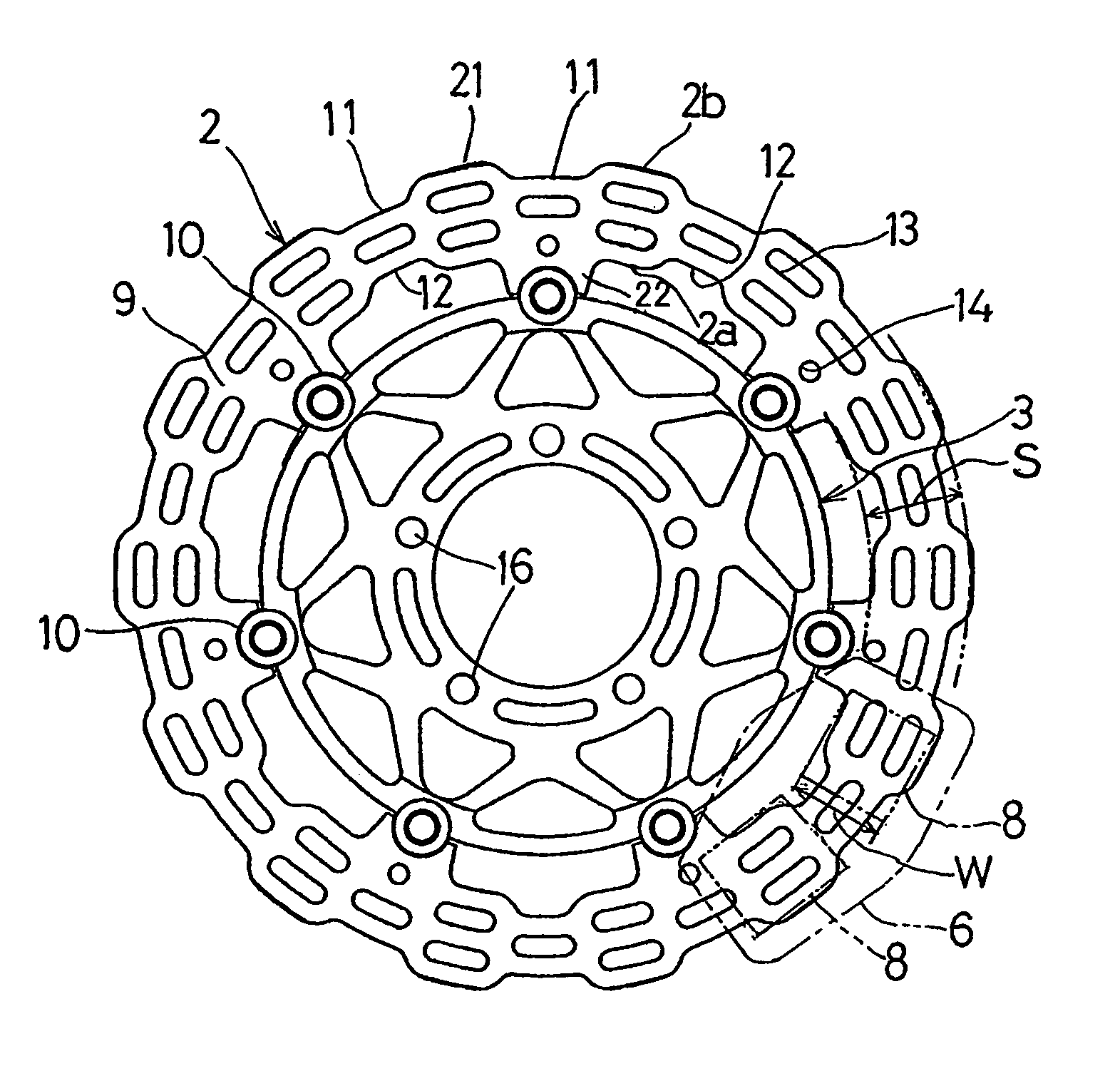
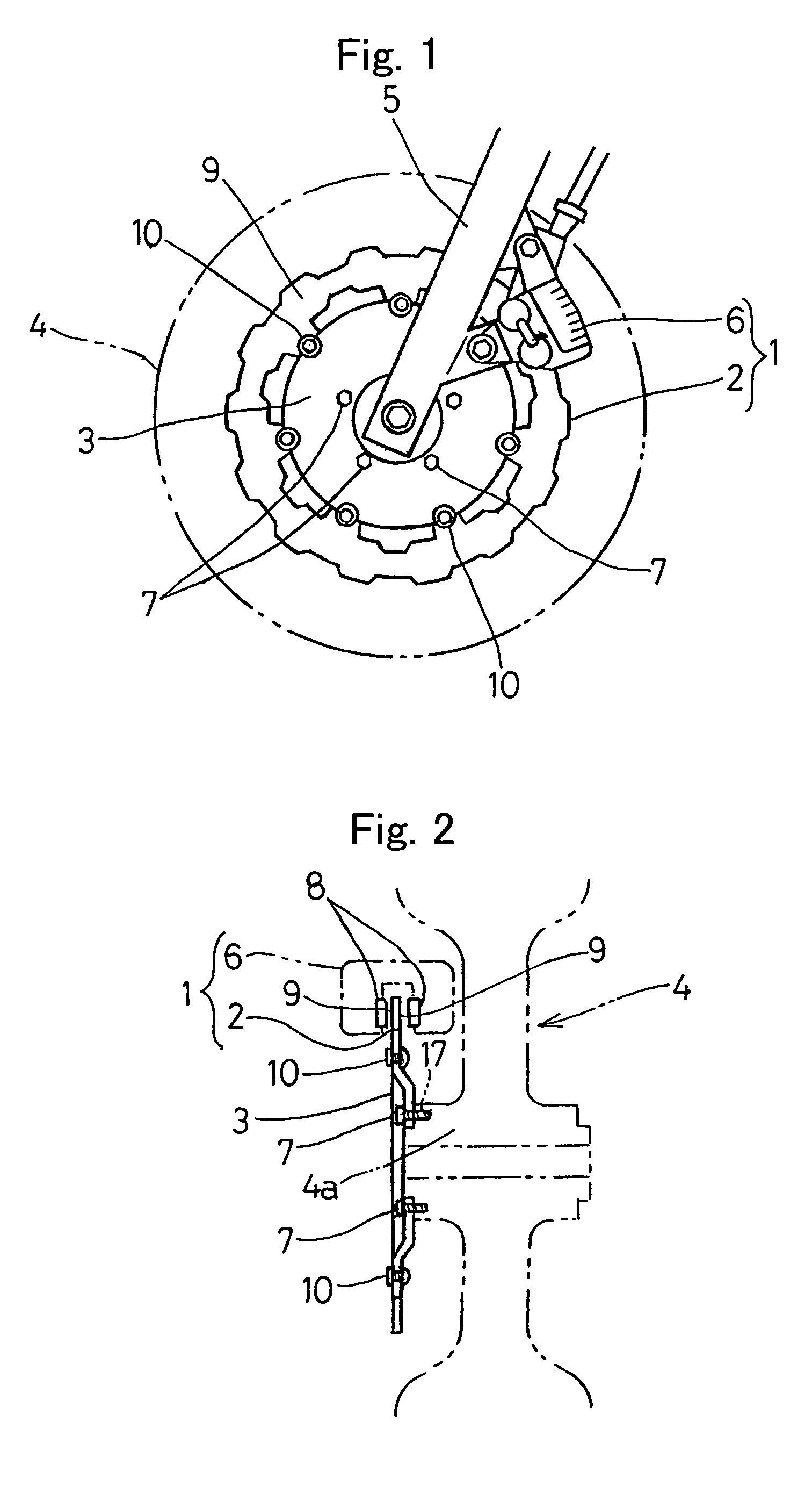
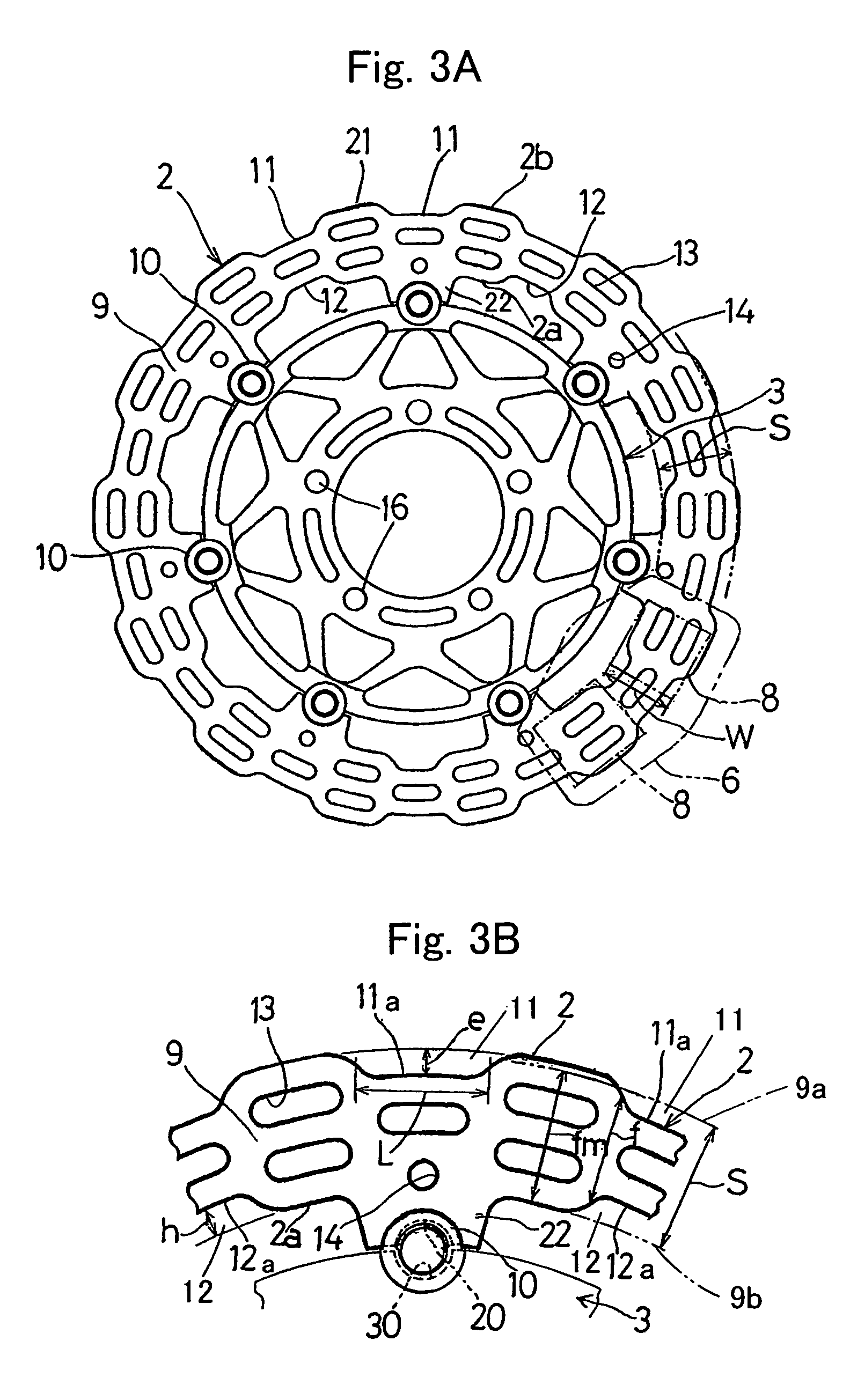
[0029]Hereinafter, preferred embodiments of the present invention will be described with reference to the accompanying drawings. Referring first to FIG. 1 illustrating, in a side view, a motorcycle front wheel provided with a brake disc for a vehicle according to a first preferred embodiment of the present invention, the brake disc identified by 2 forms a part of and is operatively associated with a disc brake assembly 1 that is mounted on a motorcycle. This brake disc 2 is fixedly mounted on a wheel 4 for rotation together therewith and has braking surfaces 9 and 9 opposite to each other. The disc brake assembly 1 also includes a caliper 6 mounted on a motorcycle body structure, for example, a front fork 5. As shown in FIG. 2, the brake disc 2 is fixedly mounted on the wheel 4 through a disc hub 3 rigidly secured to a wheel hub 4a of the wheel 4 by a plurality of bolts 7. The caliper 6 includes left and right frictional pads 8 and 8 that can be driven through caliper pistons (not s...


PUM


Abstract

There is provided a brake disc in a disc brake for a vehicle, which can be manufactured lightweight, suppress the thermal deformation and is effective to prevent the brake noises. This brake disc (2) is supported by a wheel 4 through a plurality of support members (10) and is operable to exert a braking force when sandwiched by frictional pads (8, 8). The brake disc (2) has an outer peripheral face (2b) formed with a plurality of outer recesses (11) deploying in a circumferential direction. Accordingly, the radial width (f) of the braking surfaces (9), with which the frictional pads (8) is engageable, varies in a direction circumferentially thereof.

Description

[0001]This is a continuation-in-part application of U.S. patent application Ser. No. 10 / 492,373 filed on Apr. 12, 2004 now abandoned.BACKGROUND OF THE INVENTION[0002]1. Field of the Invention[0003]The present invention relates to a brake disc in a disc brake used in a vehicle such as a motorcycle.[0004]2. Description of the Related Art[0005]As the conventional brake disc used in motorcycles, a brake disc 50 shown in FIG. 5 has been well known (See the Japanese Design Registration No. 1151976.). The brake disc 50 has a circular outer periphery and also has an inner peripheral portion adapted to be coupled with an outer peripheral portion of a disc hub 52 by a plurality of rivet-like pins 51 arranged in a circumferential direction. When the disc hub 52 is bolted to a hub (not shown) of the wheel, the brake disc 50 is supported by the wheel through the disc hub 52. A braking force is applied to the wheel when opposite braking surfaces of the brake disc 50 are sandwiched by a pair of fr...

Claims


Application Information

Patent Timeline
Patent Type & Authority Patents(United States)
IPC IPC(8): F16D65/10B62L1/00F16D65/12F16D69/00
CPCB62L1/005F16D65/12F16D2065/026F16D2065/1348F16D2069/004
Inventor OKABE, YASUHISA
Owner KAWASAKI MOTORS LTD
Why Eureka
Try Eureka