Method and foot switch control for fast angulation changes in an x-ray system

a technology of x-ray system and angulation change, which is applied in the direction of electrical equipment, medical science, diagnostics, etc., can solve the problems of difficult for physicians to accurately position the x-ray system in space to generate a two-dimensional image that captures all of the desired information, and the system is significantly more expensive than the monoplane system. , the view is limited, and the effect of reducing the difficulty of the physician

a technology of x-ray system and angulation change, which is applied in the direction of electrical equipment, medical science, diagnostics, etc., can solve the problems of difficult for physicians to accurately position the x-ray system in space to generate a two-dimensional image that captures all of the desired information, and the system is significantly more expensive than the monoplane system. , the view is limited, and the effect of reducing the difficulty of the physician

US7331711B2Active Publication Date: 2008-02-19SIEMENS HEALTHCARE GMBH

Image

  • Method and foot switch control for fast angulation changes in an x-ray system
  • Method and foot switch control for fast angulation changes in an x-ray system
  • Method and foot switch control for fast angulation changes in an x-ray system

Examples


Embodiment Construction

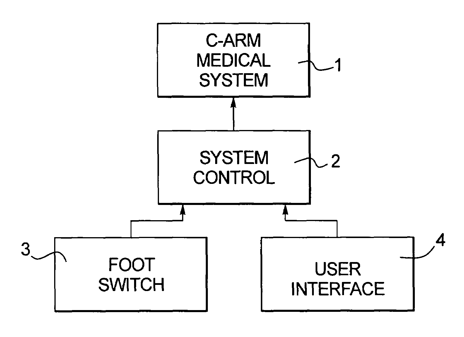
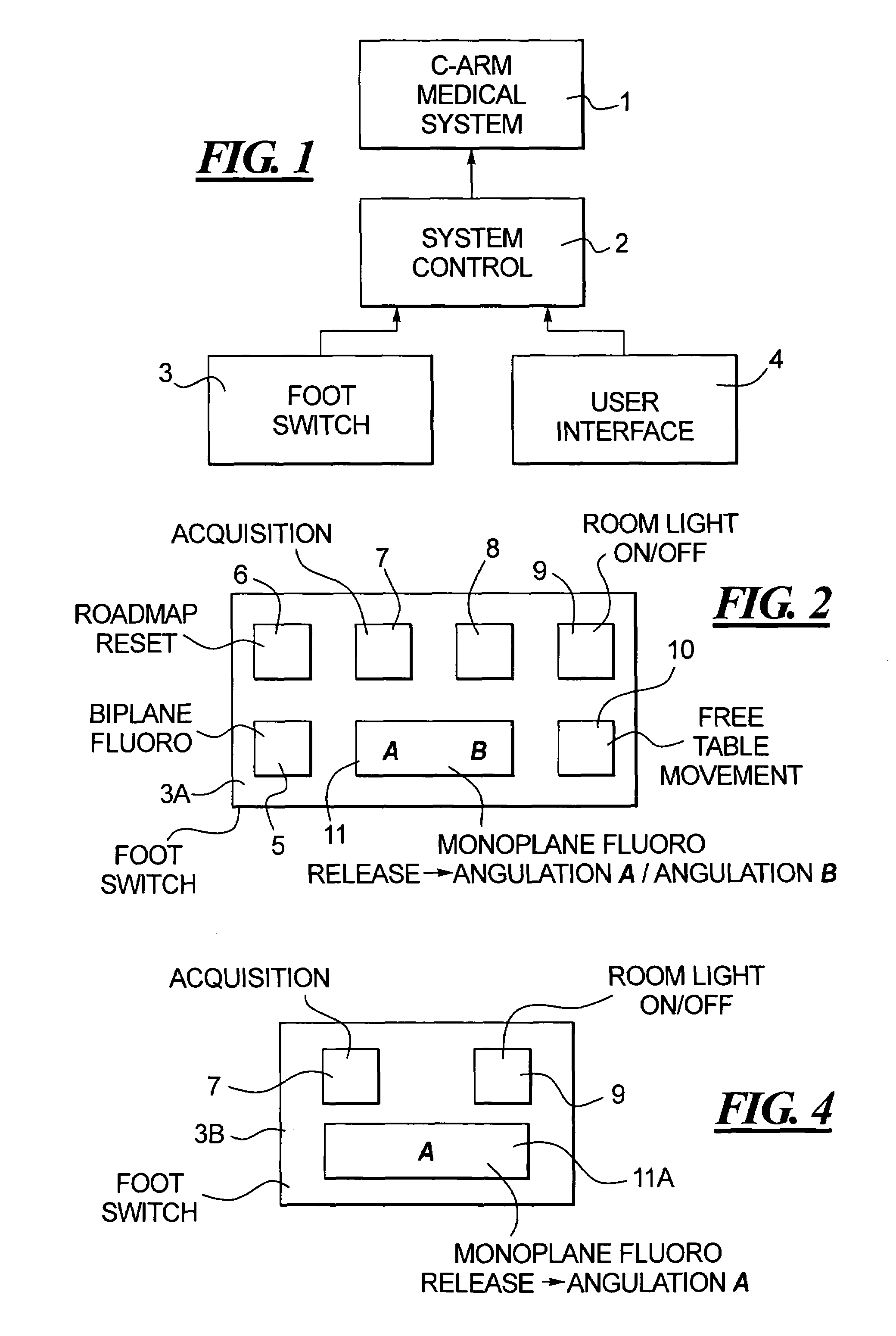
[0024]FIG. 1 illustrates the basic components for operating a medical system 1 in accordance with the present invention. The medical system 1 may be, for example, a biplane angiography system. The medical system 1 is operated by a computerized system control, to which operating commands can be provided via a flip switch 3 and a separate user interface 4, such a keyboard, mouse, touch display, etc.

[0025]A first embodiment of the foot switch 3A in accordance with the invention is shown in FIG. 2. This embodiment of the foot switch 3A has a conventional arrangement of foot pedals, that include a food pedal 5 for biplane fluoro, a foot pedal 6 for roadmap reset, a foot pedal 7 for image acquisition that, when depressed, triggers emission of x-rays, a foot pedal 8 that can be used or not used as needed, a foot pedal 9 that controls the room light (on / off), and a foot pedal 10 that freeze (releases or enables) movement of the table on which the patient is lying.

[0026]A foot switch of the ...


PUM


Abstract

In a method for fast angulation changes in a C-arm x-ray system, and a foot switch for effecting such fast angulation, a pedal of the foot switch that normally has a function not related to angulation of the C-arm is either permanently, or temporarily programmed, to operate as a pedal that, when depressed, automatically moves the C-arm to a predetermined angulation. The pedal can be movable between two positions, in order to selectively, automatically move the C-arm to either of two predetermined angulation positions, or can be used in conjunction with another pedal for that purpose. The pedal can also be temporarily given a security function and / or a radiation triggering function.

Description

BACKGROUND OF THE INVENTION[0001]1. Field of the Invention[0002]The present invention relates to a method for effecting fast angulation changes of the C-arm of an x-ray system, as well as to a foot switch control for effecting such fast angulation changes.[0003]2. Description of the Prior Art[0004]X-ray systems are commonly used for medical diagnostic purposes as well as medical interventional procedures that have an x-ray source (x-ray tube) that emits x-ray radiation that penetrates an examination subject and is detected by a radiation detector disposed opposite to the x-ray source. The x-ray source and the radiation detector are movable relative to the patient, such as by being mounted on a rotatable C-arm or some other type of movement-facilitating mechanism. The angle that a center ray, emitted by the x-ray source and proceeding to the radiation detector, makes with respect to a predetermined axis, usually the vertical axis, is defined as the angulation of the x-ray system, and...

Claims


Application Information

Patent Timeline
19 Feb 2008
Publication
US7331711B2
IPC
H05G1/02
CPC
A61B6/4441; A61B6/542
Inventors
SANDKAMP, BERNHARD; BOCSE, JAN