Wavelength reference filter

Inactive Publication Date: 2005-07-07
INTEL CORP
View PDF13 Cites 8 Cited by
  • Summary
  • Abstract
  • Description
  • Claims
  • Application Information

AI Technical Summary

Problems solved by technology

Although communications standards are in place and fabrication techniques well-developed, lasers designed for stability and predictability can in fact produce inaccurate output frequencies over the device lifetime (a lifetime often specified as 25 years).
These lasers may fail to produce acceptable output bandwidths and power levels, as well.
Although useful, etalons may introduce a relatively low but nevertheless detrimental error to laser source operation.
Some of the problems stem from the physical properties of an etalon.
Such an etalon tilt, however, introduces another problem—a

Method used


Image

  • Wavelength reference filter
  • Wavelength reference filter
  • Wavelength reference filter

Examples


Embodiment Construction

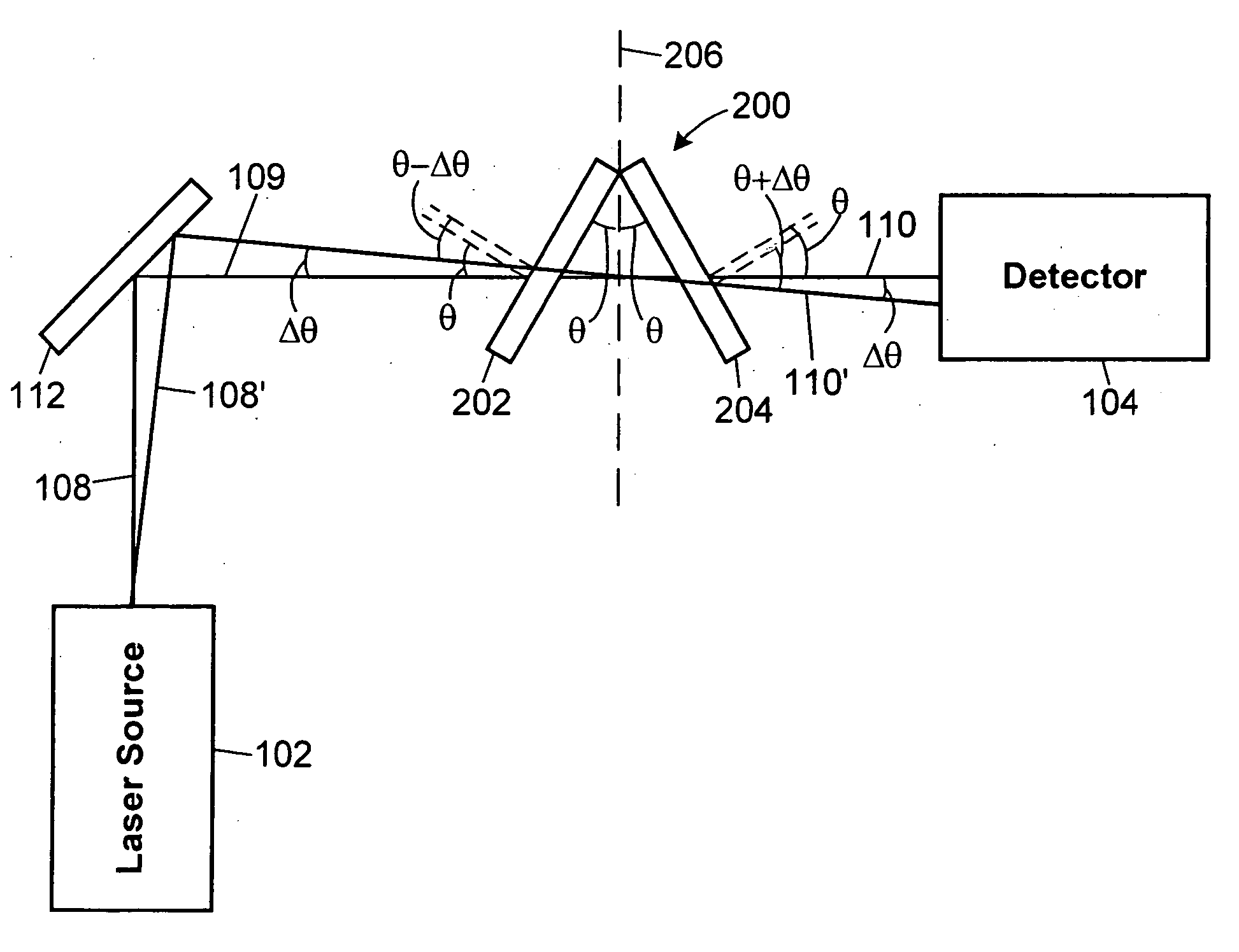
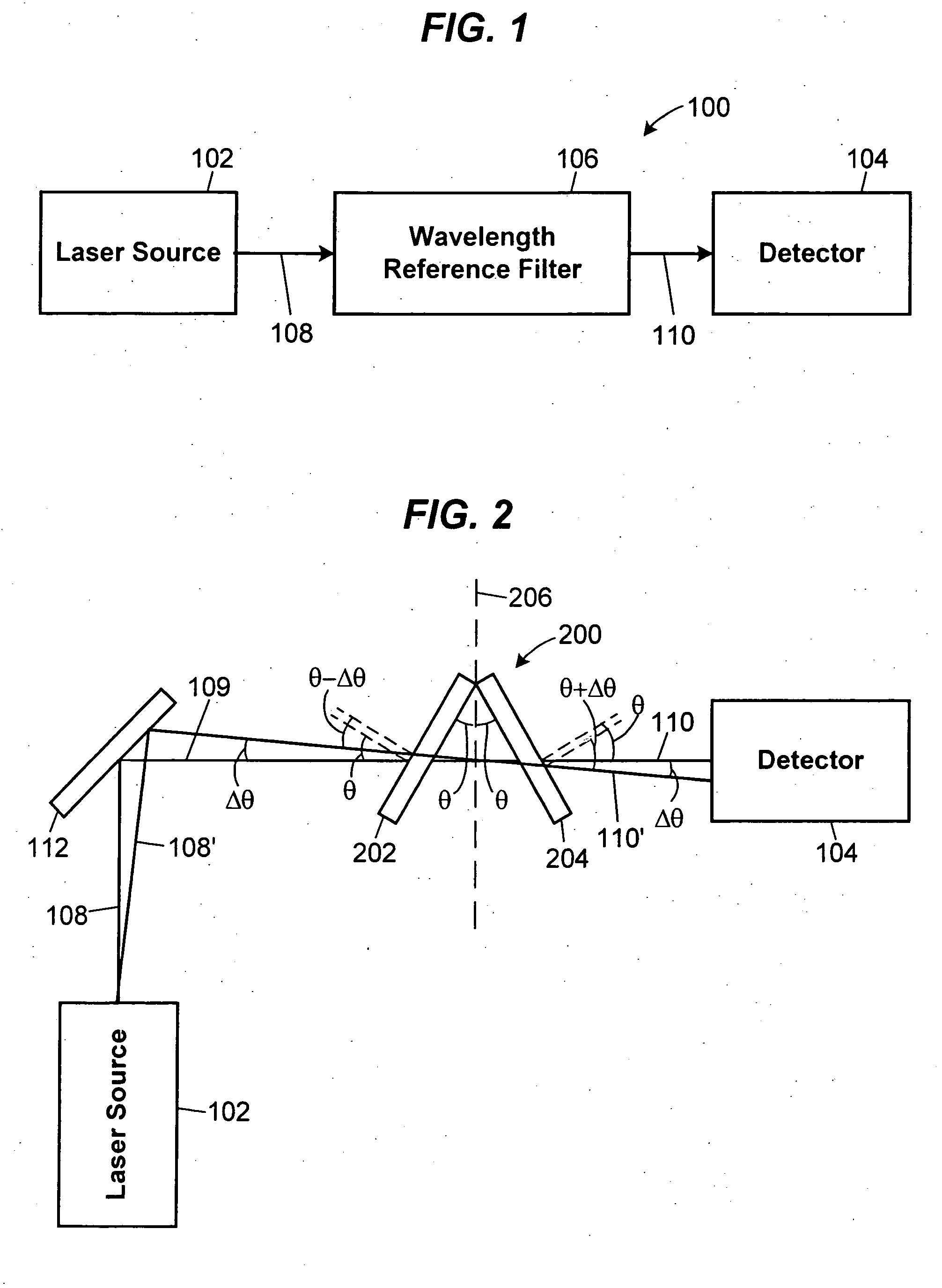
[0016]FIG. 1 illustrates an optical system 100 that may be used as a wavelength reference device, or wavelength locker. The system 100 includes a laser source 102 coupled to a detector 104. The system 100 may be used as a detector alone or as a laser source, for example, a tunable laser device with a detector for wavelength control and / or output power regulation. Example laser sources include solid state, gas, chemical, and fiber lasers. Diode lasers are commonly used in communication networks. More generally, the laser source 102 may represent other sources of an optical signal including a waveguide, fiber, free space region or lens. The detector 104 may measure frequency, amplitude, or any other metric useful to characterize an optical signal.

[0017] A wavelength reference apparatus 106 is positioned between the laser source 102 and the detector 104. The wavelength reference apparatus 106 is essentially independent of angle of incidence. As such, the incidence angle of an input be...


PUM


Abstract

A wavelength reference filter for receiving an input signal and producing a filtered output signal is provided. The operation of the filter is independent of the angle of incidence of the input signal. As a result, the output signal from the filter will maintain its wavelength, even under changes in the direction of propagation of the input signal to the filter. Without such incidence angle independence, a change to the input signal would change the output signal and result in inaccurate device operation. Example incidence angle independent filters may include a single etalon or multiple etalons. In the former example, a signal may traverse a single etalon twice, along paths that have different angular sensitivities relative to the etalon. In the latter example, each etalon may have an equal and opposite angular sensitivity, such that two the etalons have canceling angular sensitivities. All of the filters described and illustrated may be used in various devices, including detectors, laser sources (tunable and otherwise), and transponders.

Description

TECHNICAL FIELD OF THE DISCLOSURE [0001] This patent generally relates to laser sources and more particularly to a wavelength reference apparatus for a laser source. BACKGROUND OF THE RELATED ART [0002] Laser sources are important to data transmission in communication networks, small and large. In smaller-scale networks like local-area networks (LANs), for example, an individual laser source may be used to produce a signal at a single frequency. Modulation of that single frequency imparts the data for that signal. For larger networks such as metro-area networks (MANs), a wavelength division multiplexing (WDM) system may employ a laser source capable of producing a range of output frequencies. In this latter example, many channels that each represents a different data stream may be propagated on a single optical fiber. An example dense WDM system might include approximately one-hundred channels propagating on a single fiber, each channel emitting from a laser source capable of produc...

Claims


Application Information

Patent Timeline
IPC IPC(8): G02B26/00H01S3/10H01S3/13H01S3/137H01S5/00H01S5/0687
CPCG02B5/284G02B26/001H01S5/0687H01S5/0014H01S5/0078H01S3/137
Inventor MCDONALD, MARK
Owner INTEL CORP
Why Eureka
Try Eureka