Particle beam accelerator

a particle beam and accelerator technology, applied in the direction of instruments, mass spectrometers, beam deviation/focusing by electric/magnetic means, etc., can solve the problems of beam loss, the inability to easily form ceramic materials in any curve, etc., and achieve the effect of reducing the loss of charged particle beams

Active Publication Date: 2008-02-19
MITSUBISHI ELECTRIC CORP
View PDF3 Cites 44 Cited by
  • Summary
  • Abstract
  • Description
  • Claims
  • Application Information

AI Technical Summary

Benefits of technology

[0014]In the particle beam accelerator as described above, vibrations of the charged particle beam can be brought under control, which are generated due to a force applied to the beam in a direction other than its traveling direction, and loss of the charged particle beam can be reduced accordingly, because gap is formed in the accelerating unit of the vacuum duct, and the gap-constituting face of the vacuum duct is formed to be perpendicular both to the traveling direction of the charged particle beam while circulating in a first orbit, and to the traveling direction of the charged particle beam while circulating in a second orbit.

Problems solved by technology

However, ceramic materials can not be easily formed in any curve, which has entailed the shape of the gaps being adjusted to that of the ceramic materials.
In other words, there have been problems in that the acceleration voltage can not be applied to the orbiting charged particle beam in parallel with the beam, which causes the beam to undergo an acceleration force in a direction other than the traveling direction, and to vibrate, resulting in a beam loss.

Method used


Image

  • Particle beam accelerator
  • Particle beam accelerator
  • Particle beam accelerator

Examples


embodiment 1

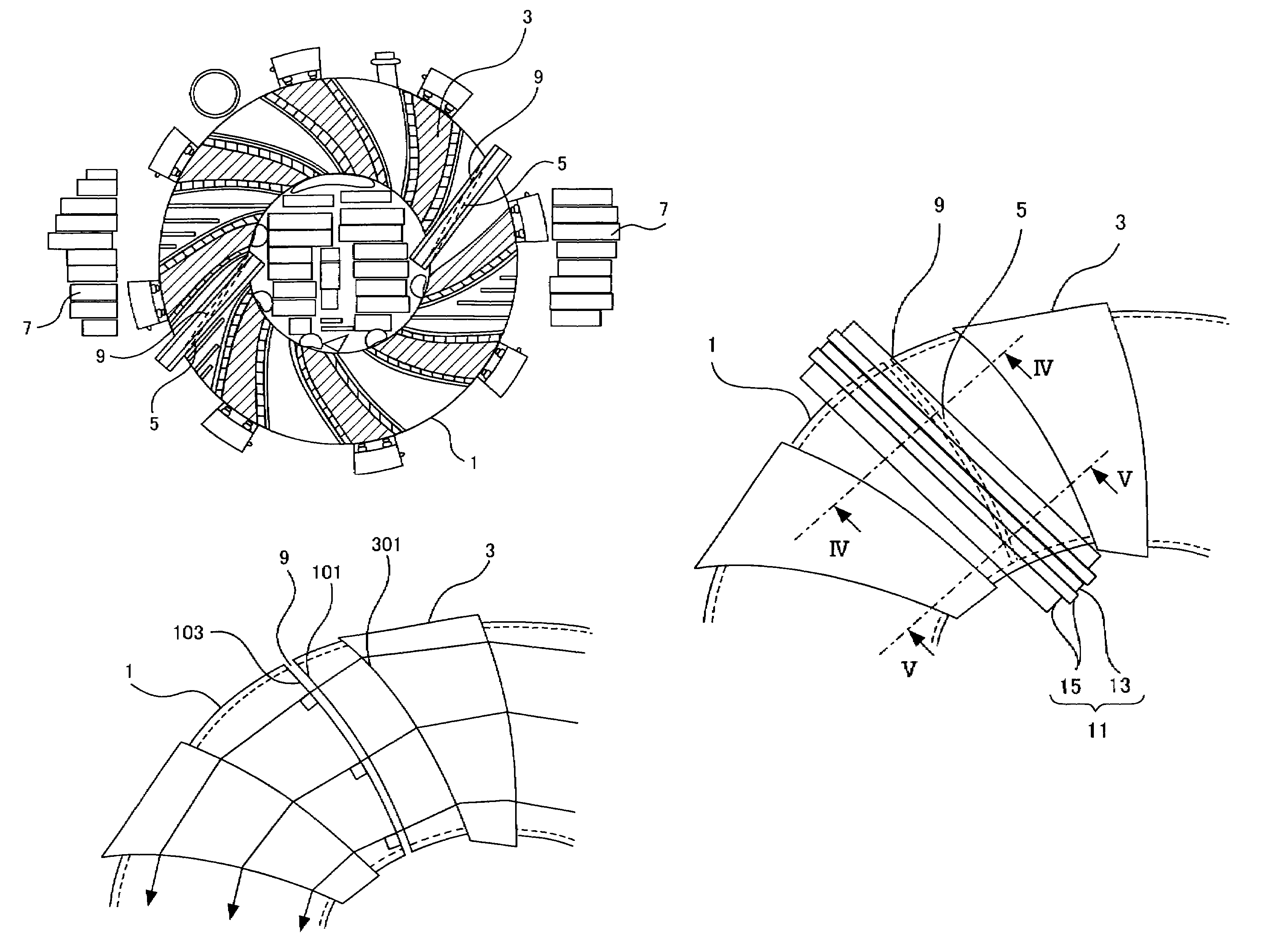
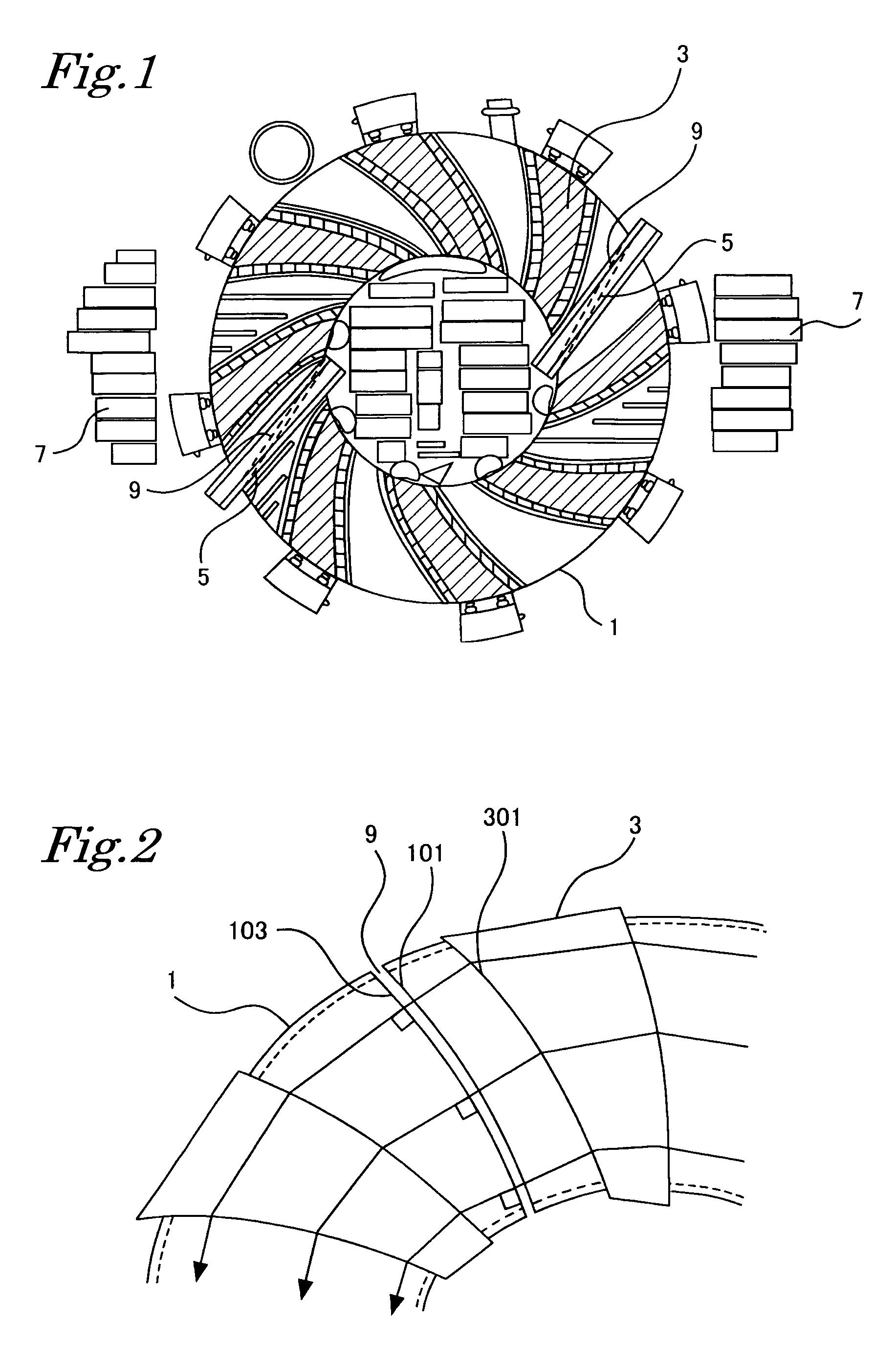
[0029]FIG. 1 is a top view illustrating a configuration of a particle beam accelerator according to Embodiment 1.

[0030]As illustrated in FIG. 1, the particle beam accelerator according to Embodiment 1 mainly comprises an annular vacuum duct “1”, a plurality of spiral-shaped-deflecting electromagnets “3”, accelerating units “5”, and accelerating cores “7”.

[0031]The vacuum duct 1 is composed by piecing stainless sheets together in an annular shape, and includes, inside the duct, sealed space having a rectangular cross-section. The sealed space is maintained in vacuum state at the time of use, and used as an annular vacuum passageway for passing a charged particle beam. As described above, the annular passageway for passing the charged particle beam is formed inside the annular vacuum duct 1, and the accelerating units 5 for accelerating the charged particle beam are disposed in the vacuum duct 1.

[0032]In the vacuum duct 1, a plurality of spiral-shaped-deflecting electromagnets 3, for ...

embodiment 2

[0048]In Embodiment 1, the particle beam accelerator has a two-fold structure in which the accelerating gap is formed in a curve, and the accelerating gap is sealed by a disc insulating member made of a ceramic material and having plane main faces. In a particle beam accelerator according to Embodiment 2, however, a vacuum duct includes flanges sandwiching a resin material, so that the gap is formed between the flanges linked together via the resin material intervening. Here, other configurations are the same as those of the particle beam accelerator according to Embodiment 1.

[0049]FIG. 8 is a diagram for explaining the accelerating gap in the particle beam accelerator according to Embodiment 2. FIG. 9 is a schematic diagram illustrating periphery of the sealing member illustrated in FIG. 8. As illustrated in FIG. 8 and FIG. 9, flanges “21” are formed on the vacuum duct 1, and a resin material “23” is sandwiched between the flanges 21. As a result, a gap is formed between the flange...

embodiment 3

[0053]In Embodiment 2, the accelerating gap is formed by sandwiching the resin material 23 between the flanges 21, which have curved faces perpendicular to the beam passing orbits, via O-rings 25. In a particle beam accelerator according to Embodiment 3, however, protrusions are provided on the resin material, and the resin material is fixed to the flanges via the protrusions. Here, other configurations are the same as those of the particle beam accelerator according to Embodiment 1.

[0054]FIG. 11 is a diagram for explaining an accelerating gap in a particle beam accelerator according to Embodiment 3. The flanges 21 are formed on the vacuum duct 1 as illustrated in FIG. 7, and the resin material 23 having protrusions is sandwiched between the flanges 21.

[0055]In order to form the accelerating gap 9 as illustrated in FIG. 11, the resin material 23, such as polyimide resin material, having the protrusions, may be sandwiched between the flanges 21 cutting the vacuum duct 1 and having cu...


PUM


Abstract

The present invention provides a particle beam accelerator for accelerating charged particles along a traveling direction of the charged particles. The invention provides a particle beam accelerator, in which the charged particle beam deflected by spiral-shaped-deflecting electromagnet 3, is accelerated by an accelerating unit 5, the charged particle beam circulating in an annular vacuum passageway of a vacuum duct 1 a plurality of times differing in orbit. And gap 9 is formed in the accelerating unit 5 of the vacuum duct 1, and gap-constituting face of the vacuum duct 1 is formed to be perpendicular to each of the traveling directions of the charged particle beam orbiting on a first orbit and on a second orbit. In the above accelerator, vibrations of the charged particle beam can be brought under control and loss of the charged particle beam can be reduced.

Description

BACKGROUND OF THE INVENTION[0001]1. Field of the Invention[0002]The present invention is related to a particle beam accelerator for generating a high-energy charged particle beam.[0003]2. Description of the Related Art[0004]Particle beam accelerators are devices for accelerating particles by applying energy to the particles, and a high-energy charged particle beam extracted from the particle beam accelerators has recently been used in various fields such as radiation treatment, including not only research but also medical fields.[0005]The particle beam accelerators are categorized into linear accelerators and annular passageway accelerators. The former are linear accelerators for accelerating particles in a linearly disposed electric acceleration field, whereas, the latter are accelerators having an annular passageway through which particles pass, and particles are accelerated by accelerating units that are disposed along the passageway, while they are orbiting in the annular passag...

Claims


Application Information

Patent Timeline
Patent Type & Authority Patents(United States)
IPC IPC(8): H05H7/00
CPCH05H15/00
Inventor INA, NOBUHIKOYAMAMOTO, YUICHINAGAYAMA, TAKAHISA
Owner MITSUBISHI ELECTRIC CORP
Why Eureka
Try Eureka