Transformer

a transformer and transformer technology, applied in transformers/inductance details, transformers/inductances magnetic cores, electrical apparatus, etc., can solve the problems of increasing the number of parts of the rectifier circuit, and increasing the size of the transformer, so as to reduce the number of turns of the secondary winding, reduce the size and cost, and increase the output voltage

Inactive Publication Date: 2008-02-19
SONY CORP
View PDF8 Cites 76 Cited by
  • Summary
  • Abstract
  • Description
  • Claims
  • Application Information

AI Technical Summary

Benefits of technology

[0013]The present invention has been made in view of such a situation, and it is desirable to provide a transformer that can provide a high voltage and is advantageous in achieving reductions in size and cost.
[0015]In the transformer according to the embodiment of the present invention, generated magnetic fluxes generated in the respective input side iron core parts by the plurality of primary windings independently pass through the output side iron core part via the connecting iron core part, whereby a total of the generated magnetic fluxes of the respective primary windings intersect the secondary winding. It is therefore possible to obtain a higher output voltage as compared with an existing transformer, and reduce the number of turns of the secondary winding. Thus, the transformer according to the embodiment of the present invention is advantageous in reducing size and cost while obtaining a high voltage.

Problems solved by technology

An increase in the number of turns of the secondary winding involves an increase in distributed capacitance within the winding, and a loss becomes greater as frequency of operation is increased.
However, such constitutions invite an increase in size of the transformer and an increase in the number of parts of the rectifier circuit, and are thus disadvantageous in reducing size and cost and securing reliability.

Method used


Image

  • Transformer
  • Transformer
  • Transformer

Examples


first embodiment

[0026]A first embodiment of the present invention will next be described with reference to the drawings.

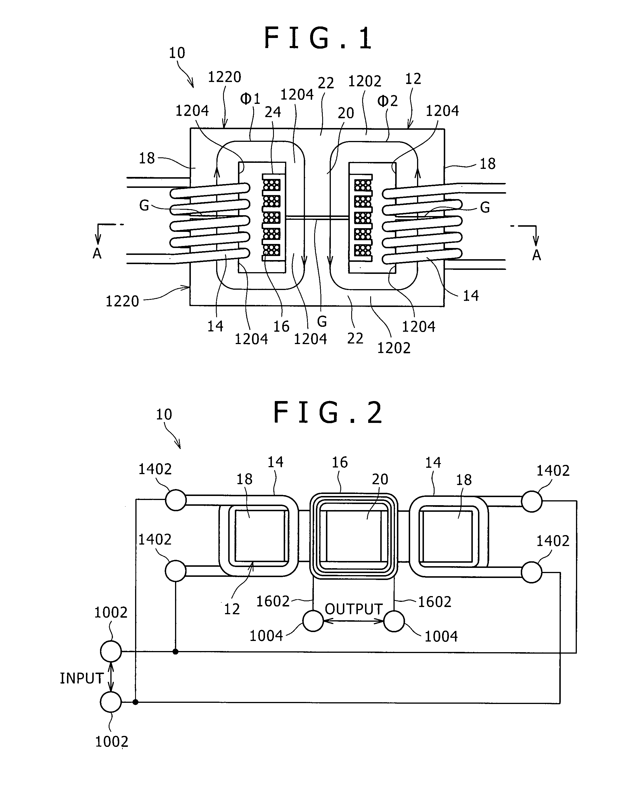
[0027]FIG. 1 is a front view of a transformer 10 according to the present embodiment. FIG. 2 is a sectional view taken along a line A-A of FIG. 1.

[0028]As shown in FIG. 1 and FIG. 2, the transformer 10 has an iron core 12 (core), primary windings 14, and a secondary winding 16.

[0029]The iron core 12 has a column-shaped output side iron core part 20, a plurality of column-shaped input side iron core parts 18 situated in the vicinity of the output side iron core part 20, and a connecting iron core part 22 for connecting both ends in a direction of length of the plurality of column-shaped input side iron core parts 18 to both ends in a direction of length of the output side iron core part 20.

[0030]The present embodiment is provided with two input side iron core parts 18 and one output side iron core part 20. The input side iron core parts 18 and the output side iron core part 20 are ...

second embodiment

[0066]A second embodiment will next be described.

[0067]The second embodiment is different from the first embodiment in that the second embodiment has three primary windings 14 and three input side iron core parts 18.

[0068]FIG. 4 is a sectional view of a transformer 10 according to the second embodiment. FIG. 5 is an exploded perspective view showing a structure of an iron core 12 of the transformer 10 according to the second embodiment.

[0069]Incidentally, in the embodiment to be described below, identical or similar parts and members to those of the first embodiment are identified by the same reference numerals.

[0070]As shown in FIGS. 4 and 5, the iron core 12 in the transformer 10 according to the second embodiment has one output side iron core part 20, three input side iron core parts 18 situated in the vicinity of the output side iron core part 20, and a connecting iron core part 22 for connecting both ends in a direction of length of the three input side iron core parts 18 to bo...

third embodiment

[0091]A third embodiment will next be described.

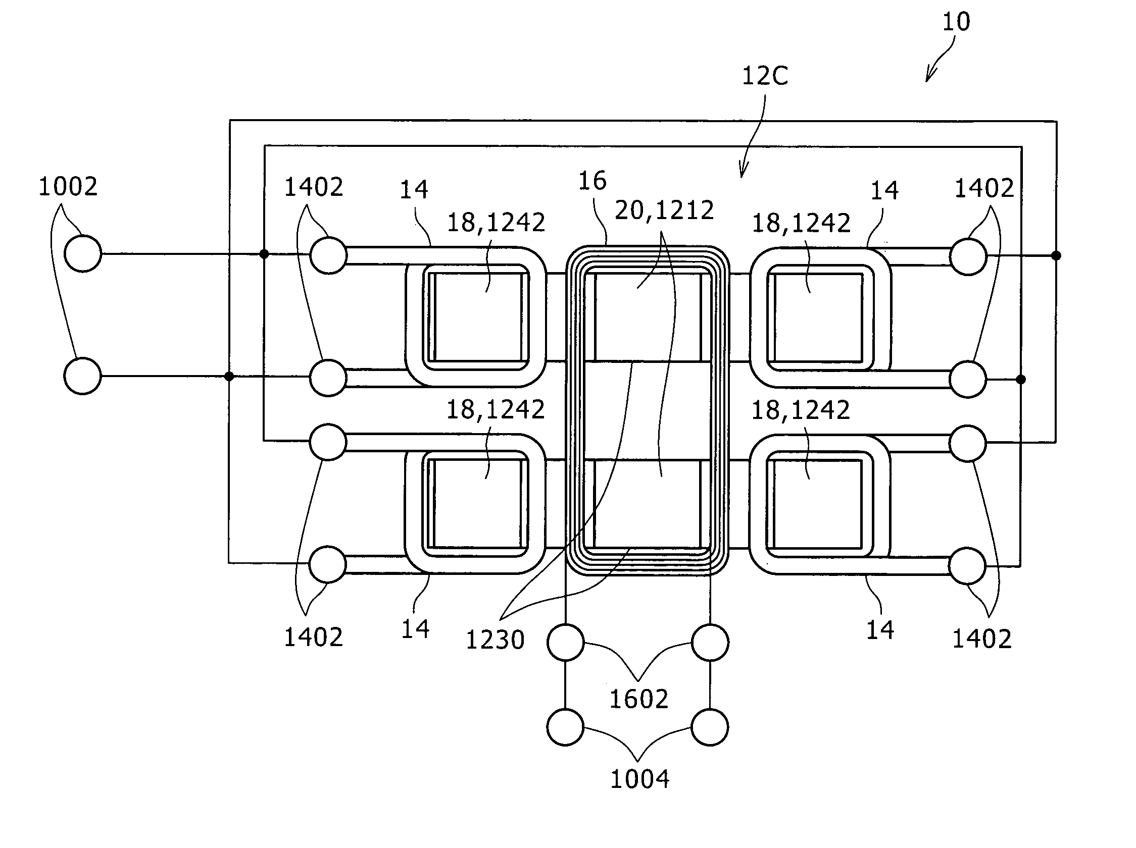
[0092]The third embodiment is different from the first embodiment in that the third embodiment has four primary windings 14 and four input side iron core parts 18.

[0093]FIG. 7 is a sectional view of a transformer 10 according to the third embodiment.

[0094]An iron core 12A in the transformer 10 according to the third embodiment has an output side iron core part 20, four input side iron core parts 18 situated in the vicinity of the output side iron core part 20, and a connecting iron core part 22 for connecting both ends in a direction of length of the four input side iron core parts 18 to both ends in a direction of length of the output side iron core part 20.

[0095]The four input side iron core parts 18 and the output side iron core part 20 are disposed in parallel with each other. The four input side iron core parts 18 are provided around the output side iron core part 20.

[0096]The primary windings 14 are wound around the four input si...


PUM

PropertyMeasurementUnit
power supply voltage Vccaaaaaaaaaa
frequencyaaaaaaaaaa
lengthaaaaaaaaaa

Abstract

Disclosed herein is a transformer including: an iron core; and a winding wound around the iron core; wherein the iron core includes a column-shaped output side iron core part, a plurality of column-shaped input side iron core parts, and a connecting iron core part, the winding includes a plurality of primary windings, a secondary winding, and generated magnetic fluxes.

Description

CROSS REFERENCES TO RELATED APPLICATIONS[0001]The present invention contains subject matter related to Japanese Patent Application JP 2006-106105 filed in the Japan Patent Office on Apr. 7, 2006, the entire contents of which being incorporated herein by reference.BACKGROUND OF THE INVENTION[0002]1. Field of the Invention[0003]The present invention relates to a transformer.[0004]2. Description of the Related Art[0005]In related art, a high-voltage generating transformer is provided in which a pair of a primary winding and a secondary winding and a rectifier circuit are integrated with each other. An output voltage of the transformer is determined by an input voltage and a turns ratio between the primary winding and the secondary winding.[0006]Hence, in order to obtain a high-voltage power when the input voltage on the primary side is low, a high turns ratio is necessary, so that the number of turns of the primary winding is decreased and the number of turns of the secondary winding i...

Claims


Application Information

Patent Timeline
Patent Type & Authority Patents(United States)
IPC IPC(8): H01F27/28
CPCH01F27/255H01F30/06
Inventor IWAI, KENJI
Owner SONY CORP
Why Eureka
Try Eureka