Multi-band antenna with wide bandwidth

a multi-band antenna and bandwidth technology, applied in the field of antennas, can solve the problems of hot r&d issue, adversely affecting the antenna gain, and bandwidth is still not wide enough, and achieves the effect of wide bandwidth, compact configuration, and easy tuning of bandwidth and impedance matching

Inactive Publication Date: 2008-02-19
HON HAI PRECISION IND CO LTD
View PDF6 Cites 242 Cited by
  • Summary
  • Abstract
  • Description
  • Claims
  • Application Information

AI Technical Summary

Benefits of technology

[0009]A primary object, therefore, of the present invention is to provide a multi-band antenna with wide bandwidth and compact configuration, and with easily tuned bandwidth and impedance matching.

Problems solved by technology

To make the miniaturized antenna supporting two or more working frequencies becomes a hot R&D issue.
However, the dielectric substrate of the antenna will introduce insertion loss, which adversely affects the antenna gain.
Additionally, though adding the loading resistor 560 can enhancing the bandwidth of the lower and the higher frequency bands, the bandwidth is still not wide enough, which restrains the application of the antenna.

Method used


Image

  • Multi-band antenna with wide bandwidth
  • Multi-band antenna with wide bandwidth
  • Multi-band antenna with wide bandwidth

Examples


Embodiment Construction

[0021]Reference will now be made in detail to a preferred embodiment of the present invention.

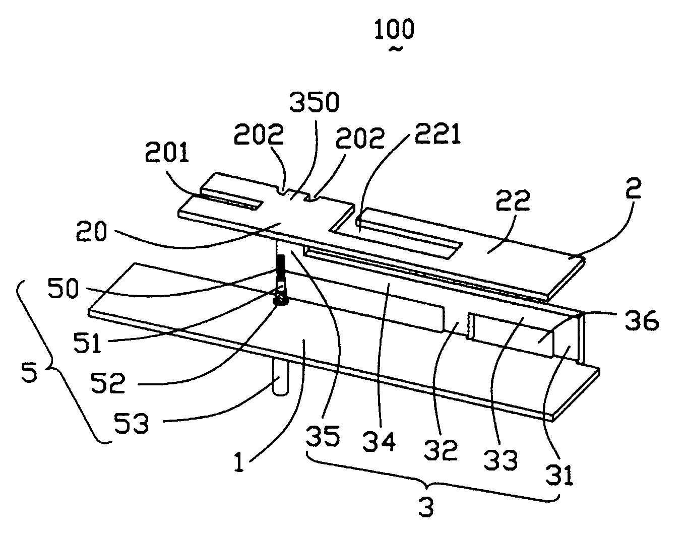
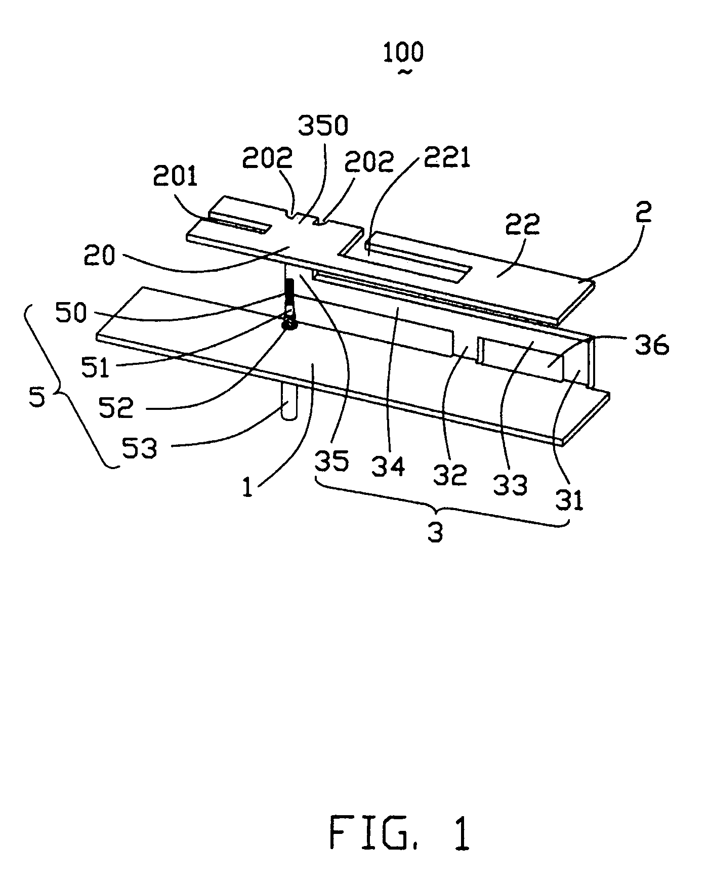
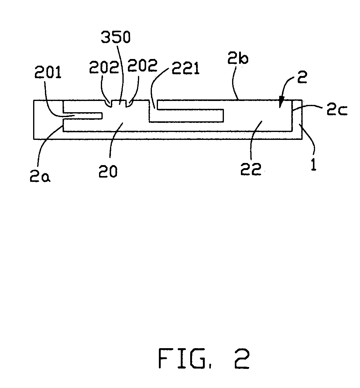
[0022]Referring to FIG. 1, a multi-band antenna 100 according to the present invention is made of metal sheet and comprises a grounding portion 1 arranged in a first plane, a radiating portion 2 arranged in a second plane parallel to the first plane and a connecting portion 3 arranged in a third plane perpendicular to the first plane and connecting the grounding portion 1 and the radiating portion 2. A feeder cable 5 is provided for feeding the antenna 100.

[0023]The connecting portion 3 is substantially inverted F-shaped and comprises a first, a second, a third, a fourth and a fifth connecting sections 31, 32, 33, 34 and 35. The first and the second connecting sections 31, 32 upwardly and vertically extend from a same side of the grounding portion 1. The third connecting section 33 connects with the first and the second connecting sections 31, 32 and is parallel to the grounding portion 1. ...


PUM


Abstract

A multi-band antenna (100) used in wireless communications includes a first radiating patch (20) arranged in a first plane and extending in a first direction, a second radiating patch (22) arranged in the first plane and extending in a second direction different from the first direction, a grounding portion (1) arranged in second plane parallel to the first plane, and an inverted F-shaped connecting portion (3) connecting the first and the second radiating patches and the grounding portion. The radiating patches define a plurality of slots (201, 202) for increasing a bandwidth of the antenna. The connecting portion defines a rectangular slot (35) for adjusting an impedance matching of the antenna.

Description

BACKGROUND OF THE INVENTION[0001]1. Field of the Invention[0002]The present invention relates generally to an antenna, and more particularly to a multi-band antenna used in an electronic device.[0003]2. Description of the Prior Art[0004]In recent years, portable wireless communication devices are becoming increasingly popular. For the design of the wireless communication device, an antenna used with it for transmitting and receiving electromagnetic waves is an important factor should be taken into account. The antenna may be mounted out of or in the device. In general use, the antenna is built-in arranged to save space and increase convenience. Considering the miniaturization trend of the wireless communication devices, the size of the antenna should be accompanylingly reduced in order to be assembled in the limit space of the communication device.[0005]Moreover, among present wireless technologies, Bluetooth running in 2.4 GHz, IEEE 802.11b / g running in 2.4 GHz and IEEE 802.11a run...

Claims


Application Information

Patent Timeline
Patent Type & Authority Patents(United States)
IPC IPC(8): H01Q13/10
CPCH01Q1/36H01Q5/371H01Q13/10H01Q9/0421
Inventor HUNG, CHEN-TATAI, LUNG-SHENGLIN, HSIEN CHUKE, YUN-LUNG
Owner HON HAI PRECISION IND CO LTD
Why Eureka
Try Eureka