
Electronic flash device and camera having the same

a technology of electronic flash and camera, which is applied in the field of electronic flash devices and cameras, can solve the problems of disadvantageous flickering of video display screens, flickering of display images, and inability to smoothly display video, so as to achieve easy control, and suppress the increase of processing load

Inactive Publication Date: 2008-02-19
FUJIFILM CORP
View PDF11 Cites 6 Cited by
  • Summary
  • Abstract
  • Description
  • Claims
  • Application Information

AI Technical Summary

Benefits of technology

[0015]The present invention has been made to solve the above problems, and has as its first object to provide an electronic flash device which can cause a camera to smoothly display a video even though preliminary emission for red-eye reduction in photographing of the video. It is the second object of the invention to provide a camera which can smoothly display a video even though preliminary emission for red-eye reduction in photographing of a video while suppressing a load of processing from being increased.

Problems solved by technology

As a result, a display screen of the video disadvantageously flickers.
Therefore, when a video is displayed by using the image signal obtained as described above, the display image flickers.
For this reason, a video is not smoothly displayed.
For this reason, a load of processing on the CPU disadvantageously increases in comparison with a case in which preliminary emission is not performed.

Method used


Image

  • Electronic flash device and camera having the same
  • Electronic flash device and camera having the same
  • Electronic flash device and camera having the same

Examples


Embodiment Construction

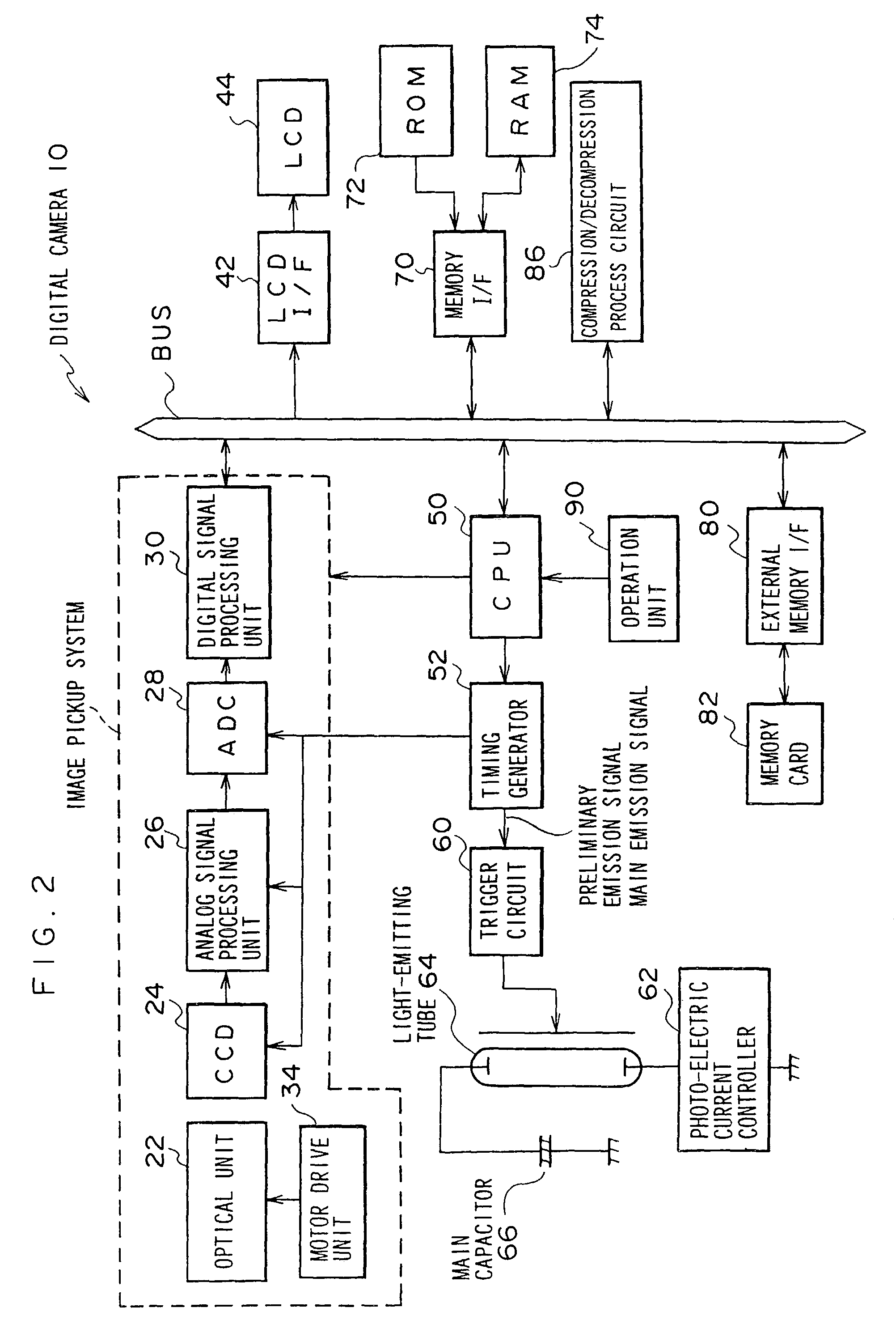
[0036]An embodiment of the present invention will be described below with reference to the accompanying drawings. An embodiment in a case in which an electronic flash device and a camera according to the invention are applied to a digital electronic still camera (to be referred to as a “digital camera” hereinafter) will be described below.

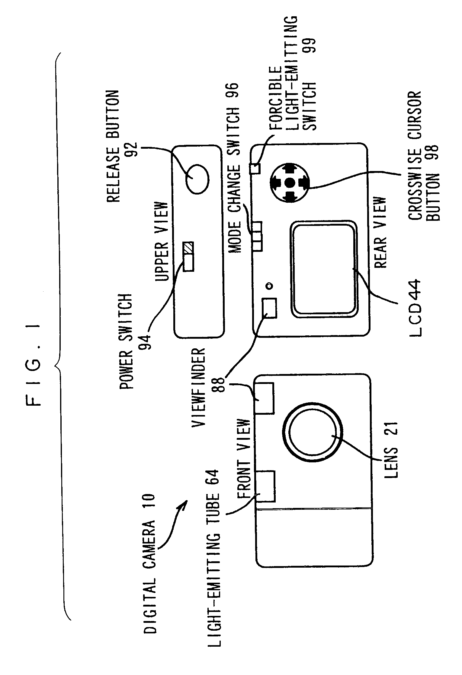
[0037]The external configuration of the digital camera 10 according to this embodiment will be described below with reference to FIG. 1.

[0038]As shown in FIG. 1, in front of the digital camera 10, a lens 21 for forming an object image, a light-emitting tube 64 for emitting light to be irradiated on an object if necessary in photographing, and a viewfinder 88 used to determine a picture composition of the object to be photographed are arranged. On the upper surface of the digital camera 10, a release button (so-called shutter) 92 which is depressed by the user when photographing is executed and a power switch 94 are arranged.

[0039]The release button...


PUM


Abstract

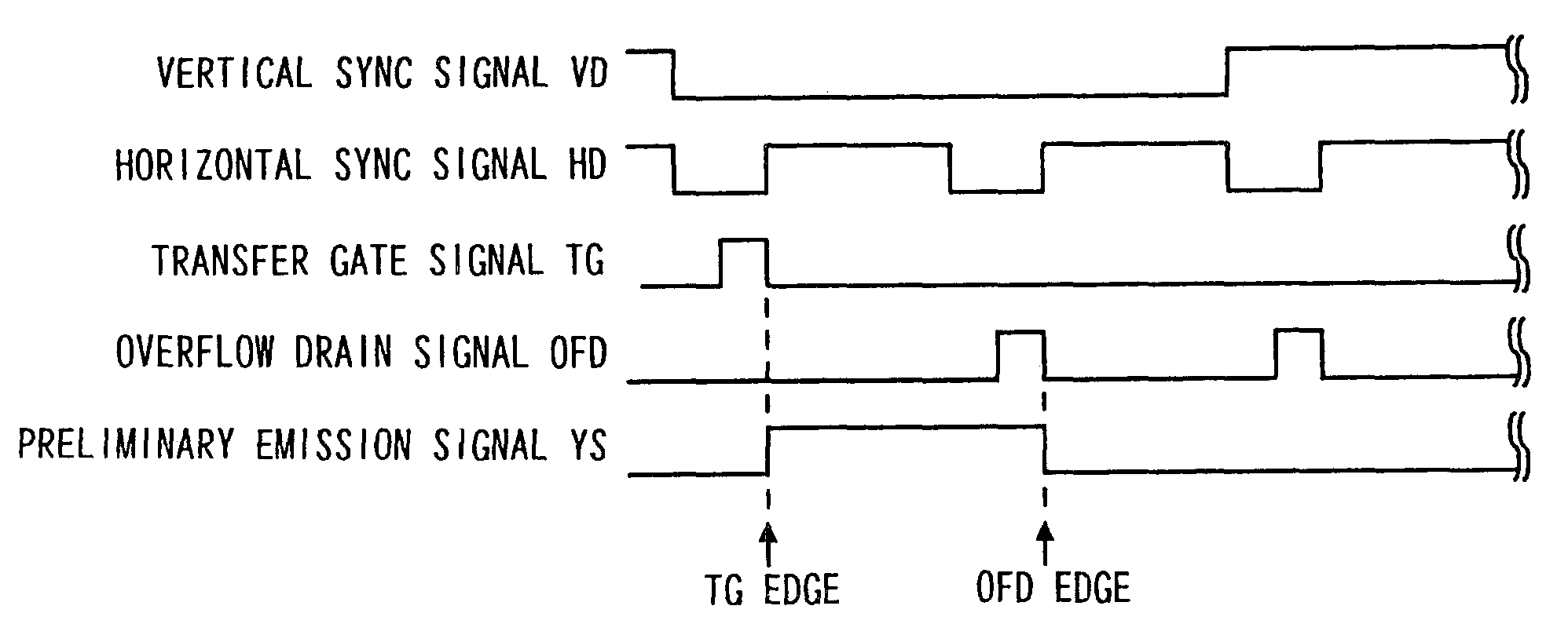
An electronic flash device and a camera which can smoothly display a video even though preliminary emission for red-eye reduction in photographing the video are obtained. A timing generator generates a preliminary emission signal such that preliminary emission for red-eye reduction by a light emitting tube is performed in a period of operation of an electronic shutter arranged in an interline CCD to input the preliminary emission signal to a trigger circuit. The timing generator sets a period in which the preliminary emission signal is set at an active level as a period corresponding to a cycle between the edge of a pulse of a transfer gate signal serving as for transferring signal charges from a light-receiving element of the CCD to a vertical transfer path and the edge of a pulse of an overflow drain signal representing a timing at which excess charges are drained by an overflow drain of the CCD.

Description

CROSS-REFERENCE TO RELATED APPLICATION[0001]This application claims priority under 35 USC 119 from Japanese Patent Application No. 2002-225969, the disclosure of which is incorporated by reference herein.BACKGROUND OF THE INVENTION[0002]1. Field of the Invention[0003]The present invention relates to an electronic flash device and a camera and, more particularly, to an electronic flash device which can perform previous light emission for red-eye reduction and a camera.[0004]2. Description of the Related Art[0005]In recent years, with an increase in resolution of an image pickup device such as a CCD (Charge Coupled Device) or a CMOS (Complementary Metal Oxide Semiconductor) image sensor, the demand for digital camera has been rapidly increasing. As digital cameras of this type, a large number of products which can photograph not only still images but also videos are commercialized.[0006]In a digital camera of this type, in general, when an object to be photographed is dark, the object...

Claims


Application Information

Patent Timeline
Patent Type & Authority Patents(United States)
IPC IPC(8): H04N5/222H04N5/335G03B15/03G03B15/05G03B17/48H04N23/75H04N25/00H04N101/00
CPCG03B7/16G03B15/05G03B2215/05G03B7/17
Inventor KUBO, NAOKI
Owner FUJIFILM CORP
Learn More