Manufacturing method of radio frequency connector

a radio frequency connector and manufacturing method technology, applied in the field of connectors, can solve the problem of difficult to precisely determine the relative position of the inner conductive pin

Inactive Publication Date: 2008-02-26
SPEED TECH
View PDF4 Cites 24 Cited by
  • Summary
  • Abstract
  • Description
  • Claims
  • Application Information

AI Technical Summary

Benefits of technology

[0018]In view of the above, in the method of manufacturing an RF connector according to the present invention, as each first joint portion and each second joint portion are correspondingly positioned to contact with each other, each center pin can be precisely positioned within each ring. Moreover, in the method of manufacturing an RF connector according to the present invention, as each first joint portion and each corresponding second joint portion are riveted together, the relative position between each center contact and the corresponding metal shell can be fixed. Further, the center contact of the RF connector in the present invention can be precisely positioned within the metal shell.

Problems solved by technology

However, as the conventional RF connector 100 has a relative small dimension, it is difficult to precisely determine the relative positions between the inner conductive pin 110 and the outer conductor 130 during the injection molding process of the dielectric body 150.

Method used


Image

  • Manufacturing method of radio frequency connector
  • Manufacturing method of radio frequency connector
  • Manufacturing method of radio frequency connector

Examples


Embodiment Construction

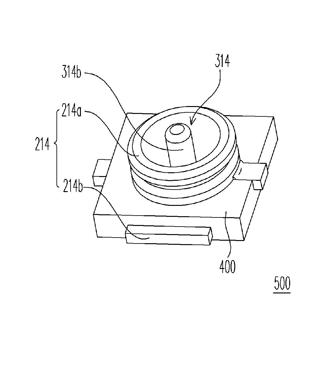
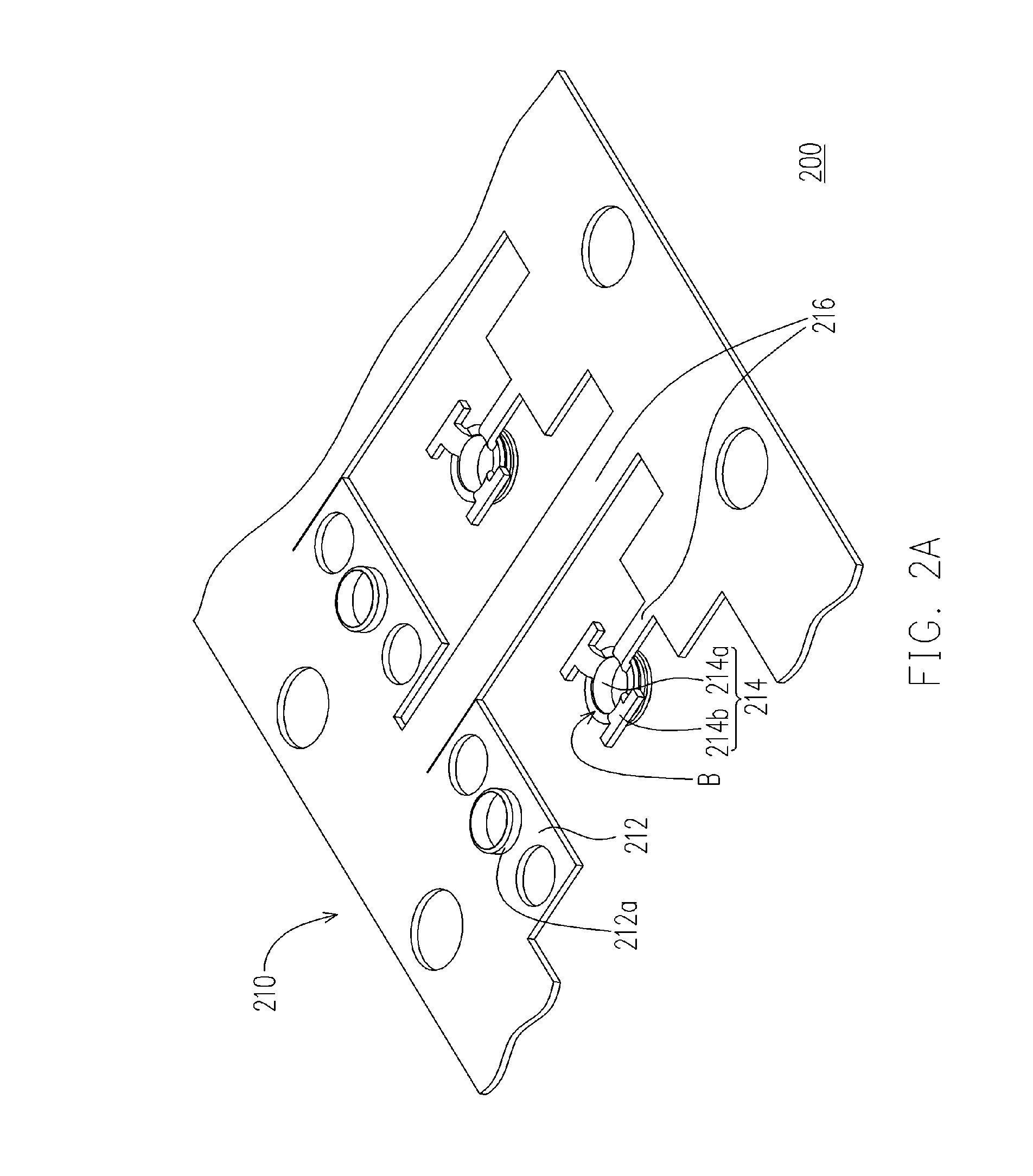
[0024]FIGS. 2A to 2F are schematic flow charts of a method of manufacturing an RF connector according to an embodiment of the present invention. The method comprises the following steps. First, referring to FIG. 2A, a first workpiece 200 with a plurality of first assembly units 210 is provided. Each of the first assembly units 210 comprises: a first joint piece 212 with a first joint portion 212a, a metal shell 214 with a ring 214a and two soldering tags 214b extending from the bottom B of the ring 214a, and a first connection portion 216 correspondingly connecting the first joint piece 212 and the ring 214a. In this embodiment, the first assembly units 210 of the first workpiece 200 are formed by punching a metal plate body (not shown).

[0025]Next, referring to FIG. 2B, a second workpiece 300 with a plurality of second assembly units 310 is provided. Each of the second assembly units 310 comprises: a second joint piece 312 with a second joint portion 312a, a center contact 314 with ...


PUM

PropertyMeasurementUnit
conductiveaaaaaaaaaa
dimensionaaaaaaaaaa
dielectricaaaaaaaaaa

Abstract

A method of manufacturing a RF connector includes the following steps. First, a first workpiece with first assembly units is provided. Each first assembly unit includes a first joint piece with a first joint portion, a metal shell with a ring and soldering tags extending therefrom, and a first connection portion connecting the first joint piece and the ring. Next, a second workpiece with second assembly units is provided. Each second assembly unit includes a second joint piece with a second joint portion, a center contact with a base and a center pin disposed thereon, and a second connection portion connecting the second joint piece and the base. Then, the first and second joint portions are positioned to contact with each other and then riveted together. Then, dielectric bodies are formed to at least correspondingly cover part of each ring and each base. Thereafter, a singularizing process is performed.

Description

BACKGROUND OF THE INVENTION[0001]1. Field of the Invention[0002]The present invention relates to a connector and a manufacturing method thereof, and more particularly, to a radio frequency (RF) connector and a manufacturing method thereof.[0003]2. Description of Related Art[0004]RF connectors play a crucial role in various electronic devices as a medium for transmitting electrical signals between the electronic devices and external devices. Recently, with the rapid development of various micro-electronic device techniques, the RF connectors have been widely used in various communication equipments (for example, mobile phones).[0005]FIG. 1 is a schematic cross-sectional view of a conventional RF connector. The conventional RF connector has been disclosed in U.S. Pat. No. 5,466,160, and the conventional RF connector 100 comprises an inner conductive pin 110, a hot-line terminal 120, an outer conductor 130, an earth terminal 140 and a dielectric body 150. The inner conductive pin 110 i...

Claims


Application Information

Patent Timeline
Patent Type & Authority Patents(United States)
IPC IPC(8): H01R43/20
CPCH01R43/24Y10T29/49956Y10T29/49218Y10T29/4922Y10T29/49016Y10T29/49204Y10T29/49208
Inventor CHEN, LI-SENZHANG, WEN-HSINGLI, JIA-WEI
Owner SPEED TECH
Why Eureka
Try Eureka