
Actuating device for a clutch

a technology of actuating device and clutch, which is applied in the direction of fluid actuating clutch, non-mechanical actuating clutch, clutch, etc., can solve the problems of difficult mounting of transmission means such as magnets and additional space, and achieve the effect of eliminating the power deflecting

Inactive Publication Date: 2008-02-26
ZF FRIEDRICHSHAFEN AG
View PDF24 Cites 7 Cited by
  • Summary
  • Abstract
  • Description
  • Claims
  • Application Information

AI Technical Summary

Benefits of technology

The invention is an actuating device for a clutch of a motor vehicle that includes an electric motor, gearing, and an accumulator. The accumulator is located inside a recirculating ball spindle, which is hollow. The accumulator can be a coil spring or multiple coil springs. The recirculating ball spindle acts as the master cylinder in a clutch actuated by fluid. The use of a hollow recirculating ball spindle allows for the placement of parts of the actuating device, such as displacement sensors. The accumulator is entirely or partially displaced in the interior of the spindle, allowing for other functions to act on the spindle or its prolongations. The technical effects of the invention include improved power support and more efficient placement of parts within the actuating device.

Problems solved by technology

If the displacement sensor is disposed parallel with the recirculating ball spindle, additional space is needed and the mounting of the transmission means such as the magnet is difficult.

Method used


Image

  • Actuating device for a clutch
  • Actuating device for a clutch
  • Actuating device for a clutch

Examples


Embodiment Construction

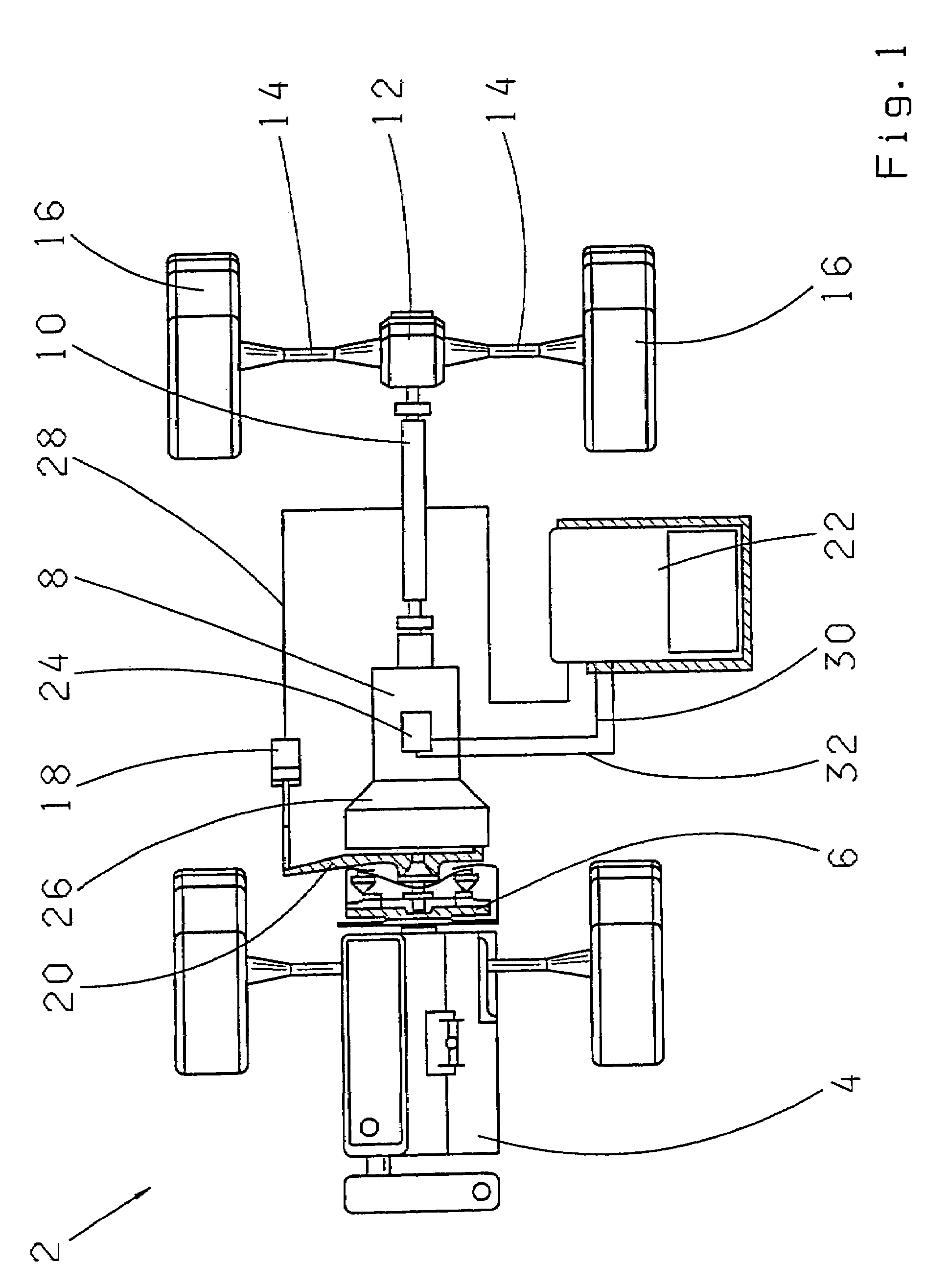
[0013]FIG. 1 shows a diagrammatic graph of a vehicle 2 having one prime mover 4 which acts via a friction clutch 6 upon one gearing 8. The gear 8 is connected via one drive shaft 10 with one differential 12 which, via a half axle 14, drives a vehicle wheel 16. The friction clutch 6 is actuated by an actuating device 18 of a clutch adjusting device 20 connected via one line 28 with a module 22. The gearing 8 is actuated by a transmission actuator 24 of a shifting device which is situated on a housing 26 of the gearing 8 and via one control cable 30 is connected with the module 22 for performing a selector motion and via a control cable 32 for performing a shift motion.

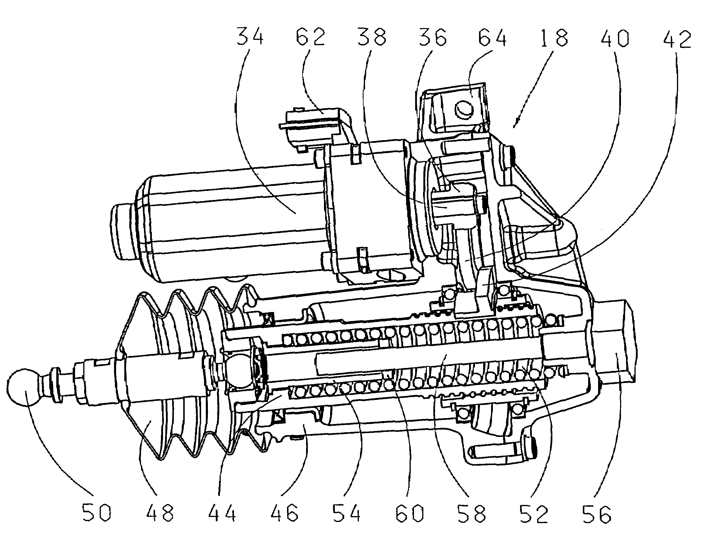
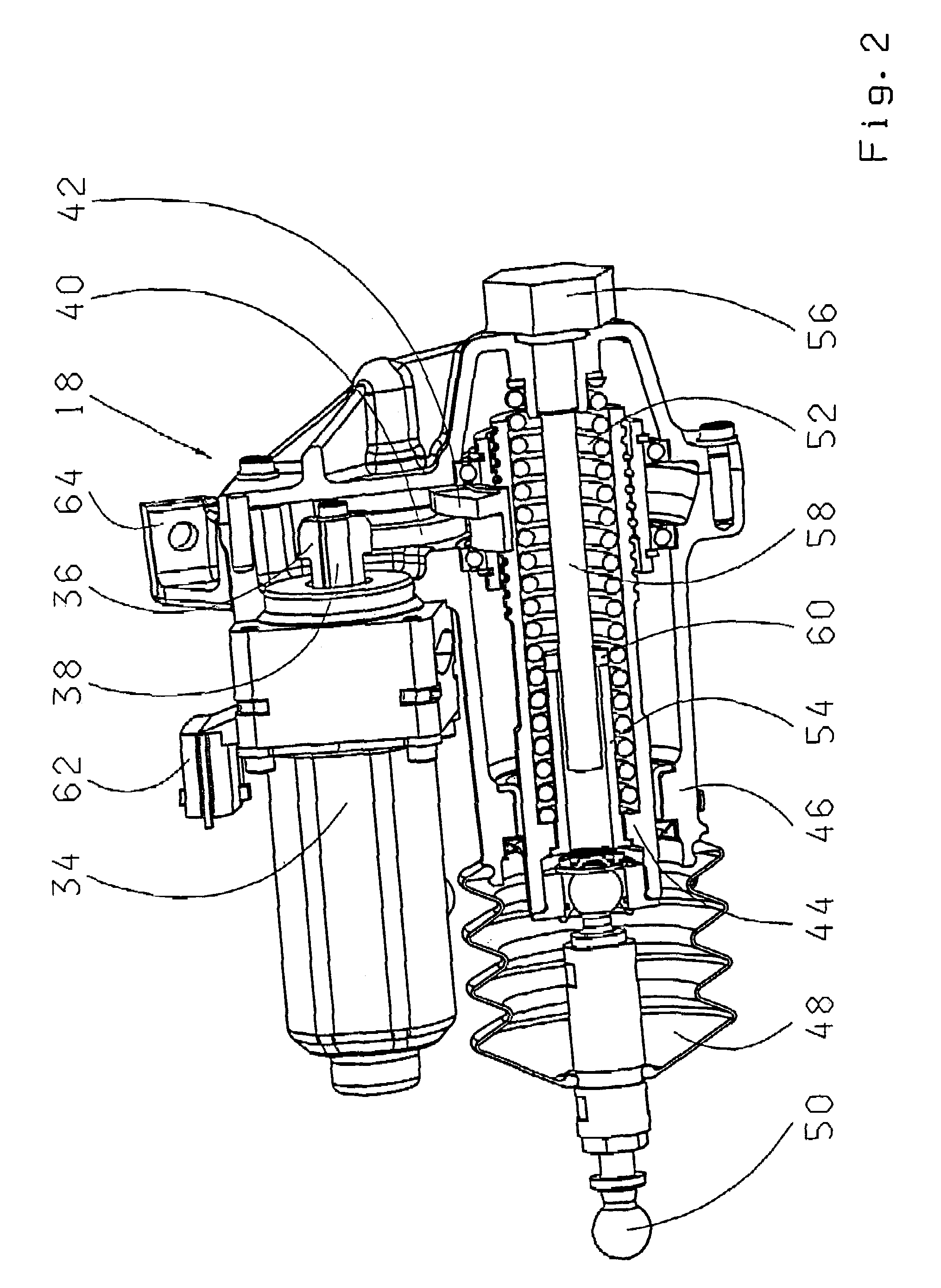
[0014]The actuating device, shown in FIG. 2, has one electric motor 34, which with a gear wheel 36 upon its output shaft 38, drives a spindle nut 42 via an intermediate wheel 30. The electric motor 34 is connected via a connecting plug 62 with the module 22 from where it draws its energy supply and its control commands....


PUM


Abstract

An actuating device (18) or a clutch (16) of a motor vehicle (2) comprising one electric motor (34), one gearing (36, 40, 42, 44) which converts rotational motion of the electric motor (34) into a translatory motion and one accumulator (52). The converter gearing comprises one recirculating ball spindle (44). The accumulator (52) is at least partly situated within the recirculating ball spindle (44), and at least parts (58, 60) of a displacement sensor (56) are situated within the recirculating ball spindle (44).

Description

[0001]This application is a national stage completion of PCT / EP2003 / 011280 filed Oct. 11, 2003 which claims priority from German Application Serial No. 102 48 829.0 filed Oct. 19, 2002.FIELD OF THE INVENTION[0002]The invention concerns an actuating device for clutches.BACKGROUND OF THE INVENTION[0003]Vehicles equipped with automated transmissions and automated clutches have been on the market for a long time. Preferred fields of use here are commercially used vehicles such as passenger cars, vans or trucks. In the recent past, passenger cars used in sports or light cars have been increasingly equipped with such transmissions or clutches. The aim is to relieve the driver from gear changes and altogether make a more comfortable and reliable operation possible. Vehicles with those transmissions usually have two pedals; an accelerator pedal and a brake pedal. The clutch pedal can be eliminated. In the vehicle, a selector switch is available for choosing the mode of operation. It is poss...

Claims


Application Information

Patent Timeline
Patent Type & Authority Patents(United States)
IPC IPC(8): F16D25/08F16D28/00F16D27/00
CPCF16D28/00
Inventor LANGWALD, OLAF
Owner ZF FRIEDRICHSHAFEN AG
Learn More