Tractor cab roof with integral HVAC air ducts

a tractor cab and air duct technology, applied in the direction of roofs, transportation and packaging, vehicle arrangements, etc., can solve the problems of cumbersome structure, inability to optimize the available space, and often unsatisfactory environmental conditions of agricultural and industrial tractors, so as to reduce the need for divider walls, compact, space efficient and functional

Active Publication Date: 2008-02-26
DEERE & CO
View PDF14 Cites 53 Cited by
  • Summary
  • Abstract
  • Description
  • Claims
  • Application Information

AI Technical Summary

Benefits of technology

[0006]The present invention provides a tractor cab roof containing integral air ducts for an HVAC system. The lower and upper roof members provide surfaces used as ducts for conditioned air and recirculating air, minimizing space requirements and reducing the need for divider walls. Fresh air from outside the tractor cab may enter through a filter located behind a rear mounted evaporator / heater core. Air recirculated from the tractor cab may be combined with fresh filtered air in an air mixing chamber just upstream of the evaporator / heater core. The tractor cab roof with integral air ducts provides a compact, space efficient and functional way of controlling air flow by using the roof surfaces, and minimizes the use of separate divider walls.

Problems solved by technology

Work vehicles such as agricultural and industrial tractors are frequently operated in less than ideal environmental conditions.
For example, tractors are operated in uncomfortably warm or cold weather, and in dusty conditions caused by the work being done by the vehicle.
This may result in a cumbersome structure which does not optimize the available space and may intrude into the cab area.
Such attempts have created their own disadvantages.
For example, roto-molded parts do not have a high degree of dimensional stability and thus present a number of fit, mount-up and aesthetic difficulties.
Further, one piece designs present less cost effective servicing access.

Method used


Image

  • Tractor cab roof with integral HVAC air ducts
  • Tractor cab roof with integral HVAC air ducts
  • Tractor cab roof with integral HVAC air ducts

Examples


Embodiment Construction

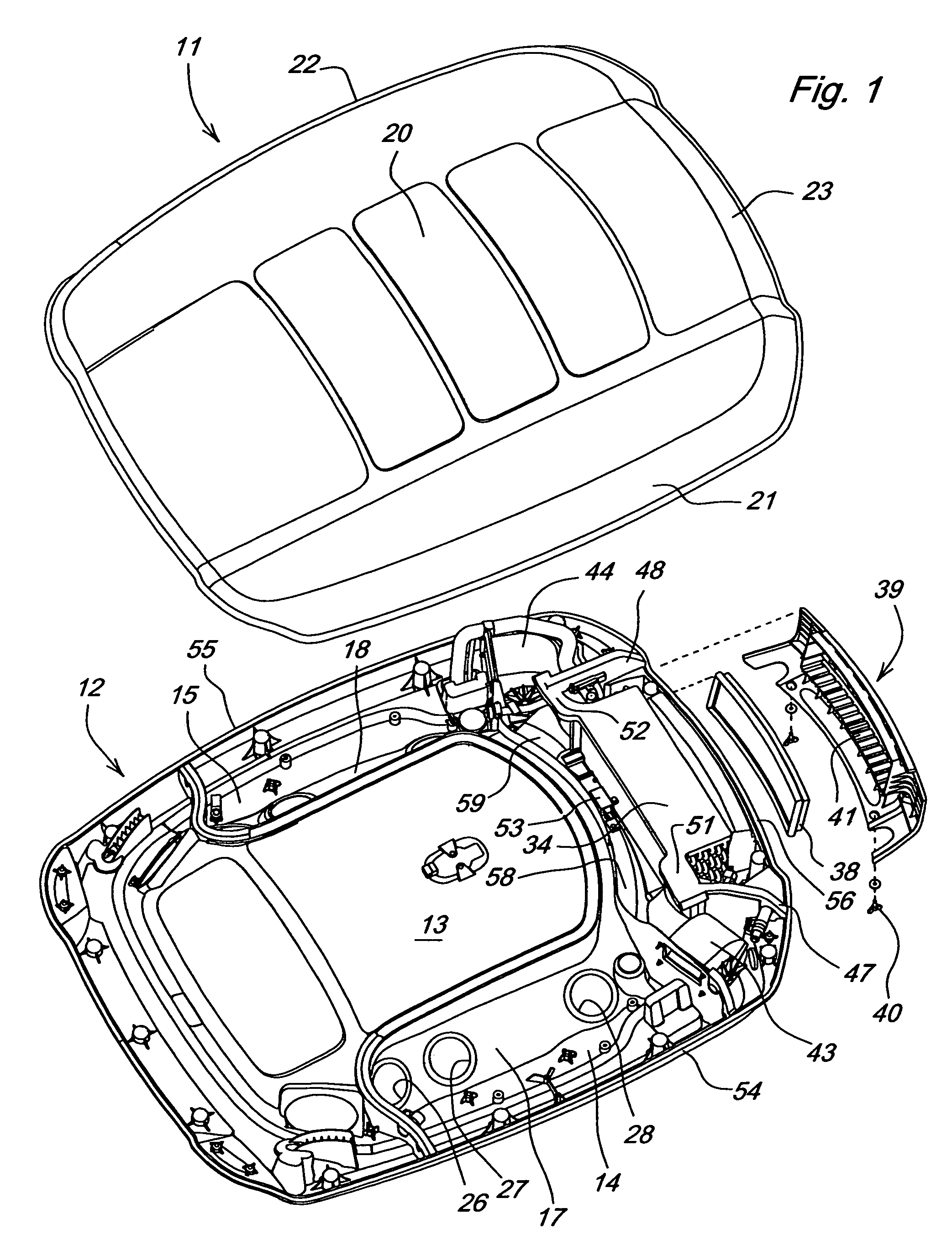
[0013]In FIG. 1 of the drawings, a first embodiment of a tractor cab roof with integral HVAC air ducts is shown. The tractor cab roof includes upper roof member 11 and lower roof member 12. The upper and lower roof geometries may provide integral ducts that minimize space requirements and the need for extra ducts.

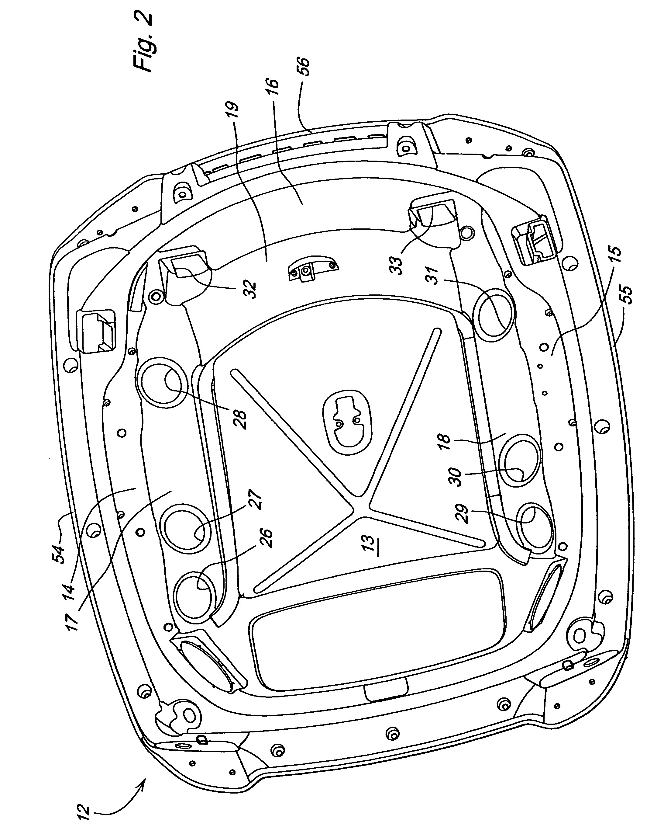
[0014]In one embodiment, upper roof member 11 may have a horizontal top panel 20 with downwardly depending side edges 21, 22 on its left and right sides, and a downwardly depending rear edge 23. As shown in FIGS. 1 and 2, lower roof member 12 may include central panel 13, left and right side panels 14, 15, and rear panel 16, which together form a unitary, integral structure. Central panel 13, left and right side panels 14, 15, and rear panel 16 may lie in generally horizontal planes, or within about ten degrees plus or minus from horizontal planes. When upper roof member 11 is mounted to lower roof member 12, top panel 20 of the upper roof member may be separated and spaced...


PUM


Abstract

A tractor cab roof with integral HVAC air ducts includes an upper roof member and a lower roof member. The upper roof member includes a top panel, downwardly depending side edges, and a downwardly depending rear edge. The lower roof member includes a central panel, left and right side panels below the central panel, a rear panel below the central panel, sloping side walls, and a sloping rear wall. Conditioned air ducts are between the upper roof member and the left and right side panels, with conditioned air outlet apertures in the sloping side walls. An evaporator / heater core is mounted on the rear panel, with an air mixing chamber to the rear and a conditioned air discharge cavity in front. Recirculating air intake apertures are provided where the sloping rear wall joins the rear panel. A pair of blowers move conditioned air from the conditioned air chamber into the conditioned air ducts. The flow of conditioned air crosses over the recirculating air in a figure eight pattern.

Description

FIELD OF THE INVENTION[0001]The present invention relates generally to a roof for a tractor cab, and more specifically to air ducts in a tractor cab roof for directing heating, cooling or ventilating air within the cab.BACKGROUND OF THE INVENTION[0002]Work vehicles such as agricultural and industrial tractors are frequently operated in less than ideal environmental conditions. For example, tractors are operated in uncomfortably warm or cold weather, and in dusty conditions caused by the work being done by the vehicle. As a result, it is desirable to provide in the cab a system for filtering and conditioning the air. One approach has been to place the components of an HVAC system in a housing in the tractor cab roof. This may result in a cumbersome structure which does not optimize the available space and may intrude into the cab area. Additionally, the ducts, hoses, conduits, wiring and inlet and outlet vents may be positioned based upon available space rather than efficient ergonom...

Claims


Application Information

Patent Timeline
Patent Type & Authority Patents(United States)
IPC IPC(8): B62D33/06
CPCB60H1/00378B60H1/00564B60H2001/00235B60H1/245
Inventor HILL, THOMAS CHILTONELHARDT, PAUL MICHAELCAUDILL, MICHAEL DAVID
Owner DEERE & CO
Why Eureka
Try Eureka