LED-tube hybrid lighting arrangement

a hybrid lighting and led tube technology, applied in the field of lighting arrangements, can solve the problems of disadvantage, scarcely able to alter the brightness of interior lighting or to vary the colour spectrum, and the loss of heat generated by the lighting arrangement is only comparatively poorly dissipated, and achieves the effect of advantageous operating properties and compact structur

Inactive Publication Date: 2008-02-26
DIEHL LUFTFAHRT ELEKTRONIK
View PDF14 Cites 68 Cited by
  • Summary
  • Abstract
  • Description
  • Claims
  • Application Information

AI Technical Summary

Benefits of technology

[0007]The object of the invention is to provide a hybrid lighting arrangement with a fluorescent lamp and at least one light emitting diode, which is intended in particular for the interior lighting of an aircraft and which is of a compact structure and which has advantageous operating properties.
[0009]The successive arrangement of the fluorescent lamp and the at least one light emitting diode makes it possible for the lighting arrangement to be of a very narrow structural form which is particularly suitable especially for use in an aircraft. In addition the light produced by the light emitting diode covers a comparatively long distance within the light guide element, until it issues into the interior space to be lit. That is advantageous in particular if a plurality of, in particular multi-coloured, light emitting diodes are provided in the lighting arrangement, especially as the light of the light emitting diodes is already mixed within the light guide element so that this avoids a spotty, ‘restless’ interior lighting effect.
[0010]Particularly uniform lighting is achieved in an embodiment of the invention which in that respect at the same time particularly saves space, in which the light guide element is in the form of a hollow shape which is substantially symmetrical with respect to the main lighting direction and which is open in the main lighting direction and in which the fluorescent lamp is at least partially received. The symmetrical configuration of the lighting arrangement has the further advantage that it is possible to use a single structural shape for the lighting arrangement on both sides of the passenger cabin of an aircraft. In contrast to an asymmetrical structure in which two mirror-image variants always have to be manufactured and stored, it is thus possible to save on manufacturing and stockkeeping costs.
[0011]Preferably, the arrangement uses a fluorescent lamp which is in the usual form of an elongate straight tube. Particularly adapted to that form of the fluorescent lamp is a light guide element which is substantially in the shape of a segment of a hollow cylinder, that is to say a hollow cylinder which is cut open along its length. Preferably the angle of opening of that hollow cylinder segment is about 180° so that the light guide element essentially assumes the shape of a hollow cylinder which has been halved along its length. Variations in the light guide element to afford larger or smaller angles of opening can however be advantageous, for adaptation to a specific lighting geometry.

Problems solved by technology

The constricted space circumstances and the necessarily good insulation of the passenger cabin of a passenger aircraft on the other hand mean that the loss heat generated by the lighting arrangement is only comparatively poorly dissipated.
With the exclusive use of fluorescent lamps however it is on the other hand scarcely possible to alter the brightness of the interior lighting or to vary the colour spectrum thereof.
That is found to be a disadvantage in many situations.
A light emitting diode however in itself has the disadvantage, in relation to a fluorescent lamp, of a comparatively low level of brightness and a comparatively high level of lost power which is dissipated in the form of heat.
Such a hybrid lighting arrangement however frequently takes up a comparatively large amount of space and therefore for precisely that reason can be only limitedly used in an aircraft.

Method used


Image

  • LED-tube hybrid lighting arrangement
  • LED-tube hybrid lighting arrangement

Examples


Embodiment Construction

[0021]Mutually corresponding parts and parameters are denoted by the same references in the Figures.

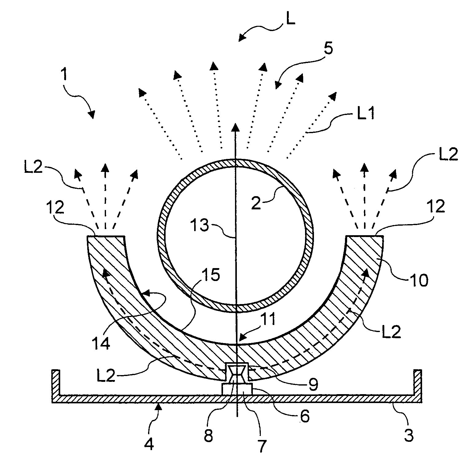
[0022]The lighting arrangement 1 illustrated in FIG. 1 includes a fluorescent lamp 2 which is in the form of a straight elongate tube and which is contacted at both longitudinal ends by means of holders (not shown) and which is fixed at a spacing to a carrier plate 3. The surface of the carrier plate 3, which is remote from the fluorescent lamp 2, is referred to hereinafter as the rear side 4. In a corresponding manner therefore the fluorescent lamp 2 is arranged at the front side 5 of the lighting arrangement 1.

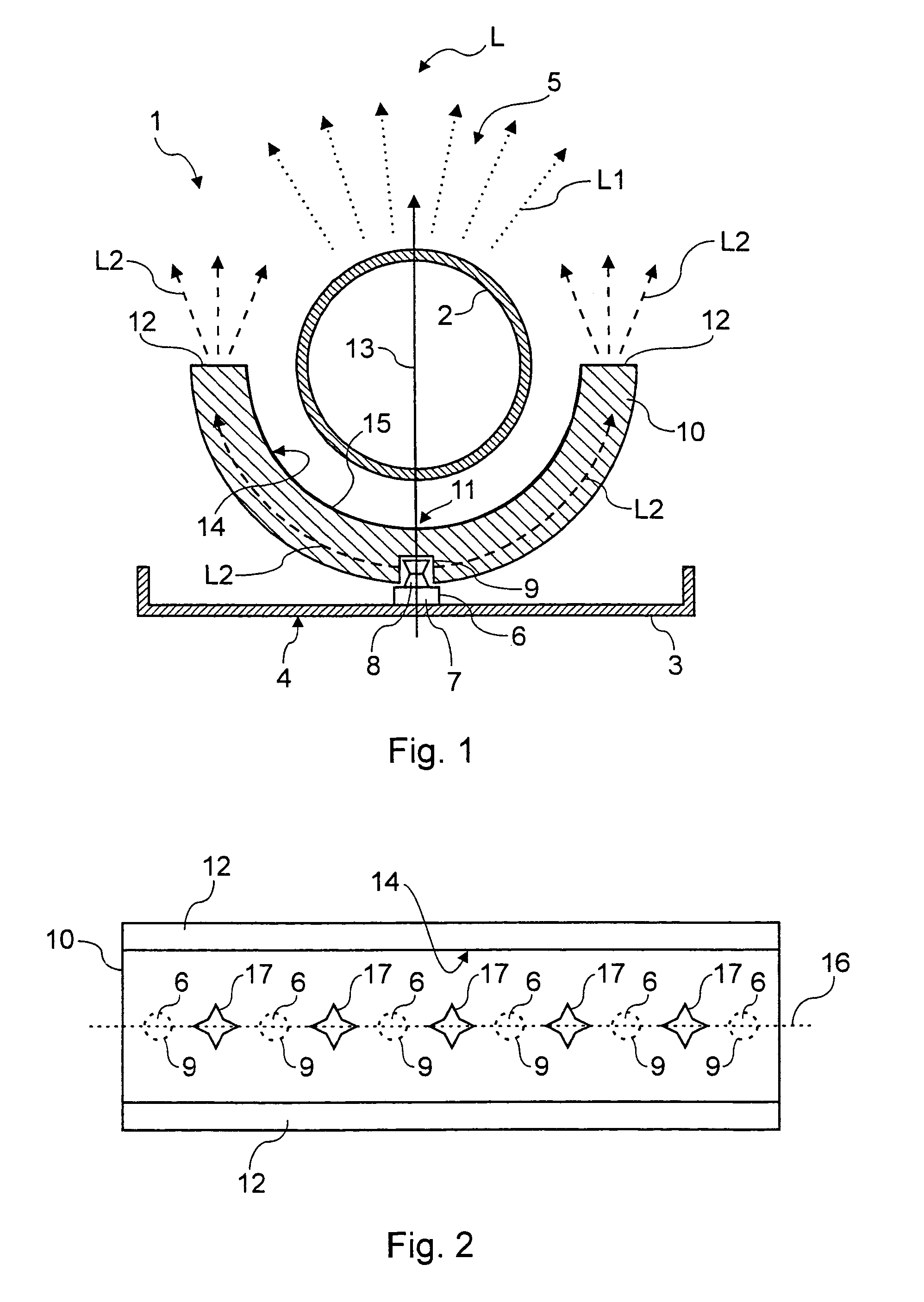
[0023]The lighting arrangement 1 further includes a number of light emitting diodes 6 which are arranged in a row at spacings from each other along the fluorescent lamp 2 (see FIG. 2). Each light emitting diode 6 is mounted with its contact end 7 on the surface of the carrier plate 3, which faces towards the fluorescent lamp 2, and is thus arranged between the carrier plate 3 ...


PUM

PropertyMeasurementUnit
angleaaaaaaaaaa
shapeaaaaaaaaaa
colorsaaaaaaaaaa

Abstract

A lighting arrangement (1) of a space-saving configuration, including a fluorescent lamp (2) and at least one light emitting diode (6), which is suitable in particular for use for interior lighting of an aircraft. In this case the light emitting diode (6), viewed in the direction of a main lighting direction (13), is arranged behind the fluorescent lamp (2). The lighting arrangement (1) further includes a light guide element (10) which is adapted to guide light (L2) emitted by the light emitting diode (6) past the fluorescent lamp (2) and emit it substantially in the main lighting direction (13).

Description

BACKGROUND OF THE INVENTION[0001]1. Field of the Invention[0002]The invention relates to a lighting arrangement comprising a fluorescent lamp (or tube) and at least one light emitting diode (or LED), which is provided in particular for the interior lighting in a vehicle, in particular in a passenger aircraft.[0003]2. Discussion of the Prior Art[0004]Hitherto fluorescent lamps have predominantly been used for illuminating the interior of an aircraft. The user of fluorescent lamps is advantageous insofar as they make it possible to produce white light with a frequency spectrum which is pleasant for the human eye, with a particularly high light yield. The advantage of a high light yield is of great significance in particular in regard to the interior lighting of a vehicle, especially as here on the one hand the space available for lighting units is seriously restricted. The constricted space circumstances and the necessarily good insulation of the passenger cabin of a passenger aircraf...

Claims


Application Information

Patent Timeline
Patent Type & Authority Patents(United States)
IPC IPC(8): F21V7/04F21K99/00B60Q3/00B60Q3/02C02F1/28F21S8/00F21V8/00F21W106/00F21W107/30F21Y113/20G02B6/00
CPCB60Q3/004B60Q3/025G02B6/0021B64C2027/8236B64D2011/0038C02F1/281F21V2200/13F21Y2103/00F21Y2113/00F21Y2113/02G02B6/0068F21Y2101/02B60Q3/43B60Q3/64F21Y2113/20F21Y2115/10
Inventor KLETTKE, OLIVER
Owner DIEHL LUFTFAHRT ELEKTRONIK
Why Eureka
Try Eureka