Method and apparatus for locating the trajectory of an object in motion

a technology of motion trajectory and detection system, which is applied in the direction of sports equipment, instruments, and reradiation, can solve the problems of system not addressing the saturation effect of the sun, not addressing the exposure of arrays to ambient light, and unable to determine the velocity, nor the direction of threa

Active Publication Date: 2008-02-26
VISUAL SPORTS SYST
View PDF12 Cites 36 Cited by
  • Summary
  • Abstract
  • Description
  • Claims
  • Application Information

AI Technical Summary

Benefits of technology

[0022]According to a feature of the invention, two linear detection arrays may be said to constitute a “set of arrays”. By employing a pair of such sets, each set providing respective, shared, common fields of view, an accurate measurement can be made of the position of the tracked object at two locations. This can be used to establish the local trajectory or the line of travel of an object. In the case of a launched projectile, e.g. a golf ball, for which the takeoff point is known, the initial parabolic path of such projectile can be established without taking time measurements. Recording the time between the successive intersections of the object with the respective common fields of view allows the object's immediate velocity to be established. This provides a further means for determining the initial parabolic path of a projectile.
[0029]A further feature of the invention is that over-saturation of the photosensitive array due to excessive illumination, as by the sun, can be achieved by using photodiode arrays with an “anti-blooming” control as well as by the use of wave-length selective optical filters and / or photosensitive optical filtering that darkens when exposed to intense light, i.e., an auto-darkening, photochromic optical filter.

Problems solved by technology

The patent does not address the exposure of the arrays to the ambient light.
The system does not address the saturation effect of the sun on the area CCD sensor in the camera.
However, it cannot determine the velocity, nor the direction of the threat.
Furthermore, this patent application does not mention how to prevent the over saturation of the diode array when the image of the sun is focused on it.
However, such known linear arrays can only sample a planar surface in space, viewed edge-on.
While providing some image information with respect to the location of an object in space, the full location of an object, much less its trajectory, cannot be defined through use of a single linear array of directed pixel sensors.

Method used


Image

  • Method and apparatus for locating the trajectory of an object in motion
  • Method and apparatus for locating the trajectory of an object in motion
  • Method and apparatus for locating the trajectory of an object in motion

Examples


Embodiment Construction

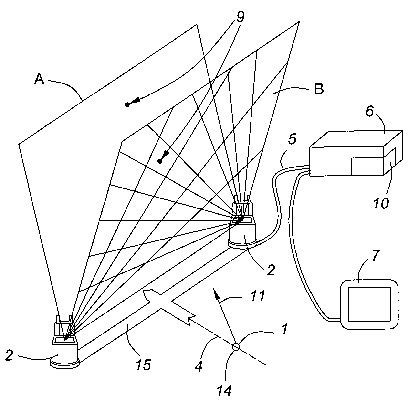
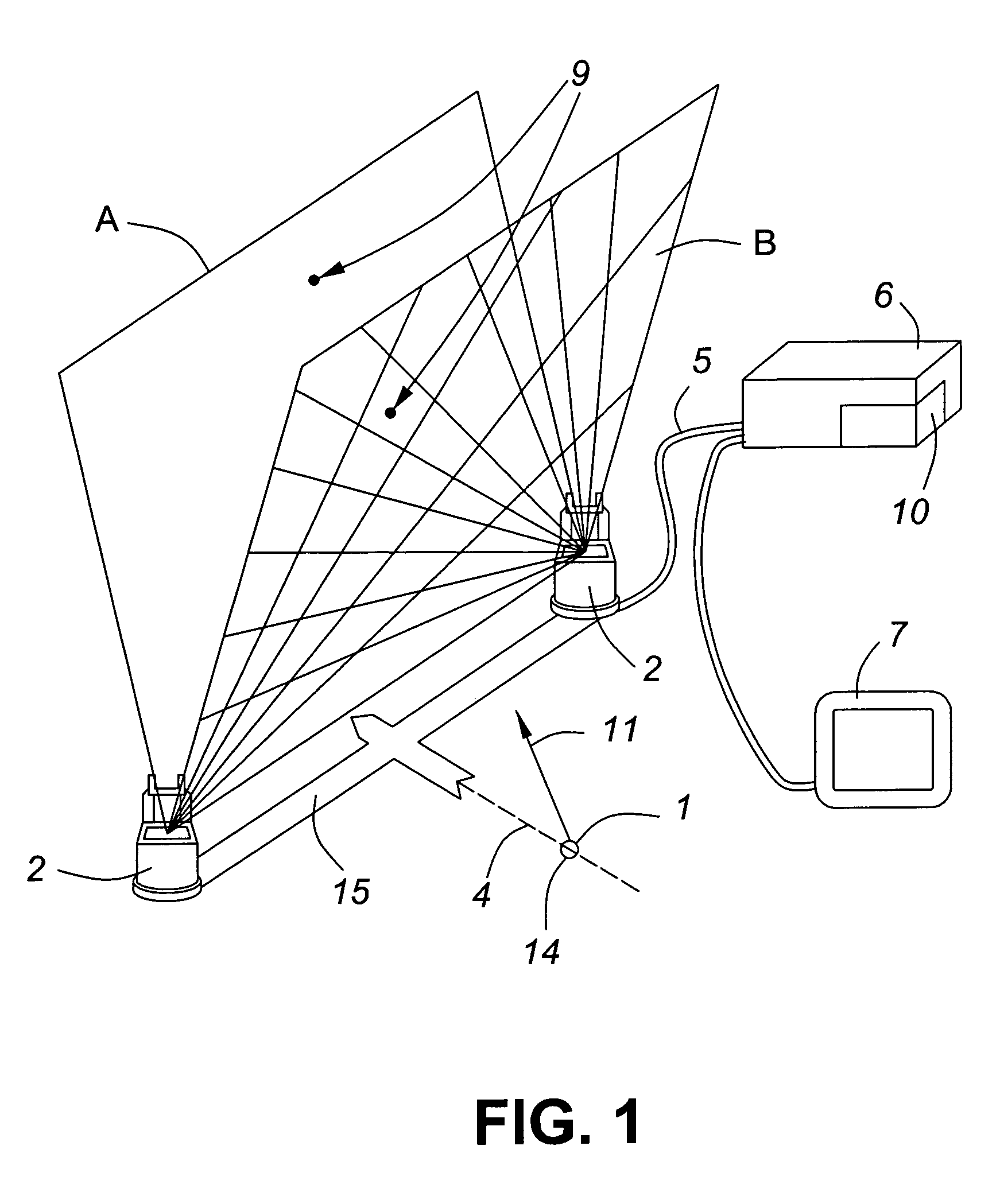
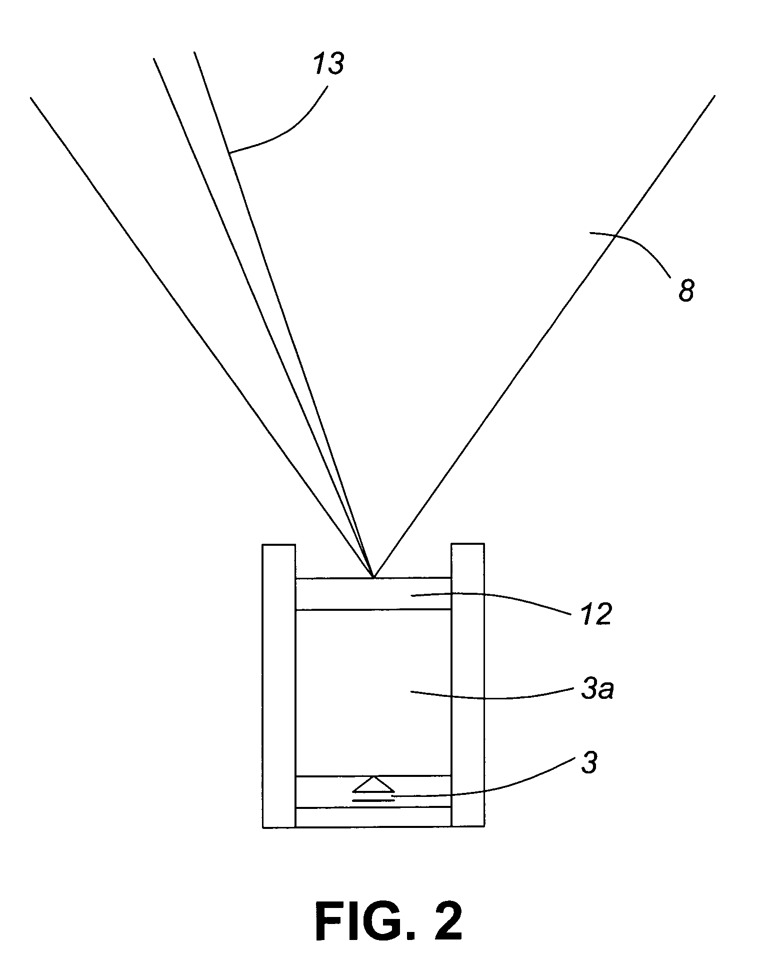
[0038]FIG. 1 illustrates the operation of the system as it tracks a golf ball 1. Two sensor pods 2, each containing two position sensor arrays 3 as shown in FIG. 2, are installed with one pod 2 on either side of the target line 4 at a known separation distance. The “target line 4” is the line over which the object to be sensed is expected to pass. The sensor pods 2 are connected electronically by a wire link 5 or a wireless link to the electronic processing unit 6. This unit sends signals to a display 7.

[0039]When the sensor pods 2 are aligned, the fields of view 8 as shown in FIG. 2 generated by each of the respective position sensor arrays 3 in one sensor pod 2 preferably overlap with the fields of view of a corresponding position sensor array 3 in the other sensor pod. This defines two common planar position sensor zones A and B. The sensor arrays 3 which combine to define a sensor zone constitute an associated set of sensor arrays, with one member of the set being present in eac...


PUM


Abstract

An object locating system detects the presence of an object as it passes through two consecutive planar fields of view. Two pairs of optical sensor arrays with multiple, directed, pixel detectors observe the object from two angles as the object passes through each consecutive field of view. The locations of penetrations of the respective fields of view are calculated by triangulation. Using this data, the known location of the take-off point and / or the delay between penetrations, the trajectory of the object in time and space is calculated. Applications include projecting the range of a driven golf ball, measuring the respective arriving and departing velocities of a hit baseball, and determining the trajectory and origin of an arriving projectile, as in the case of the threat to a military vehicle.

Description

FIELD OF THE INVENTION[0001]This invention relates to a detection system for determining the position, velocity and trajectory in space of moving objects, such as golf balls and baseballs for the purpose of training and practicing as well as other objects such as the detection of projectiles approaching a vehicle. It can also be used to evaluate the mechanical characteristics of a baseball bat, tennis racket, or the like by comparing the ball's velocity before and after the collision with the baseball bat or racket, etc. Moreover, it can accurately determine whether or not a baseball crosses the strike zone by tracking its trajectory in front of the home plate.BACKGROUND TO THE INVENTION[0002]Numerous systems exist for tracking a golf ball and estimating its range. Their main purpose is to give golfers a graphic and / or numeric display indicating their drive's effectiveness when they practice or play.[0003]U.S. Pat. No. 5,303,924 describes a golf game apparatus that simulates a total...

Claims


Application Information

Patent Timeline
Patent Type & Authority Patents(United States)
IPC IPC(8): A63B57/00A63B67/02F41H5/007G01C11/30G01S17/66
CPCF41H5/007G01P3/685G01S5/16
Inventor PETROV, DIMITRI
Owner VISUAL SPORTS SYST
Why Eureka
Try Eureka