Temperature monitoring device

Inactive Publication Date: 2008-02-26
SANYO ELECTRIC CO LTD
View PDF23 Cites 24 Cited by
  • Summary
  • Abstract
  • Description
  • Claims
  • Application Information

AI Technical Summary

Benefits of technology

[0011]According to the invention, a temperature recording device having a memory to store temperature measurement data based on measurements of temperature detector is attached to an electric power-applied section, e.g., main circuit connection or high-voltage cable. The temperature recording device is provided with a specific identification number. It transmits a temperature measurement data, which is obtained b

Problems solved by technology

If power transmission is continuously conducted in such a state, the transmission line may be broken by heat.
However, in the conventional temperature monitoring device using the thermo-sensing label, there is a problem that even when a periodical temperature change not reaching the extraordinary temperature occurs at the electric power-applied section due to an increase in amount of current

Method used


Image

  • Temperature monitoring device
  • Temperature monitoring device
  • Temperature monitoring device

Examples


Example

[0024]Temperature monitoring device for electric power-applied section of the invention is explained below in reference to the drawings.

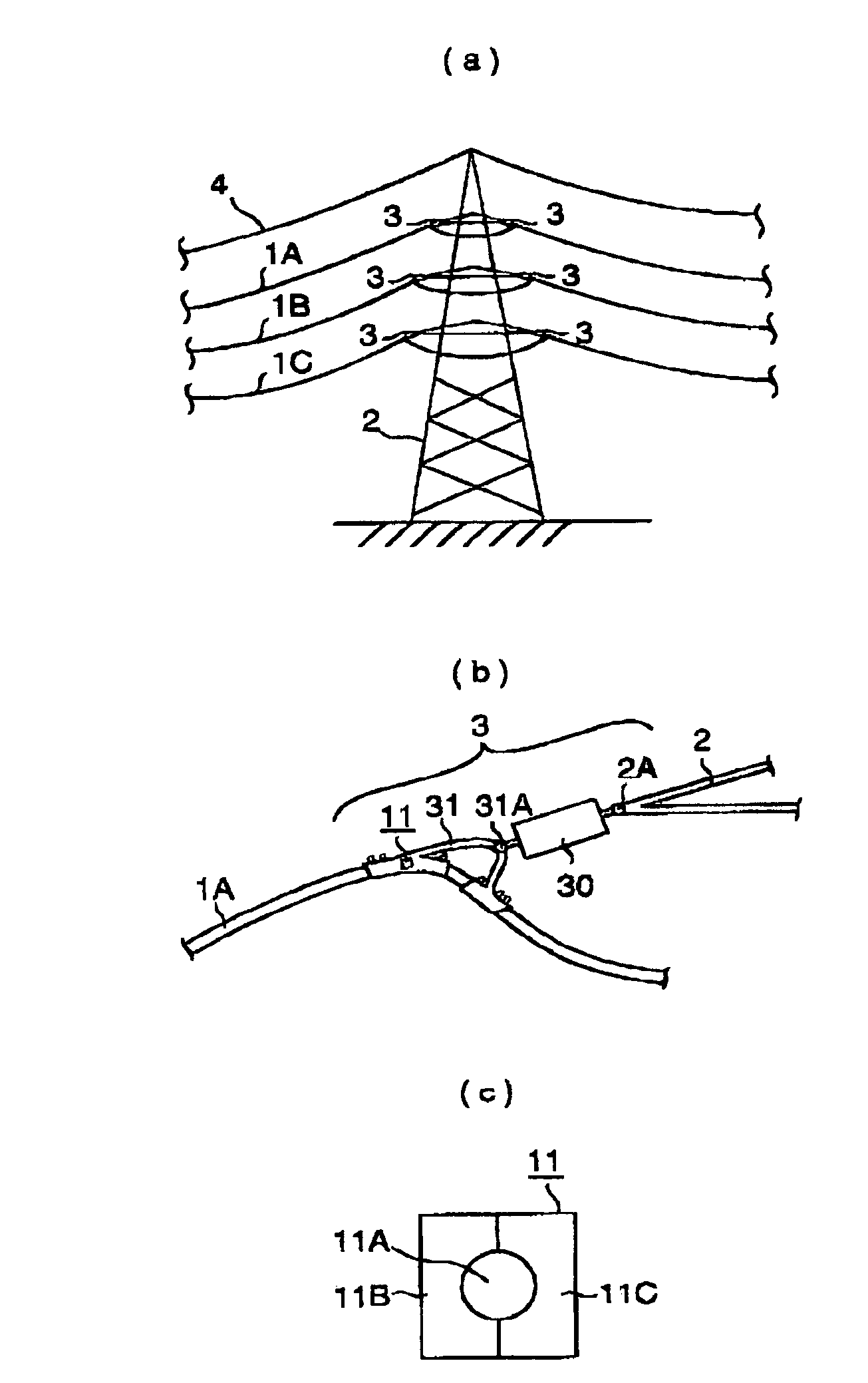
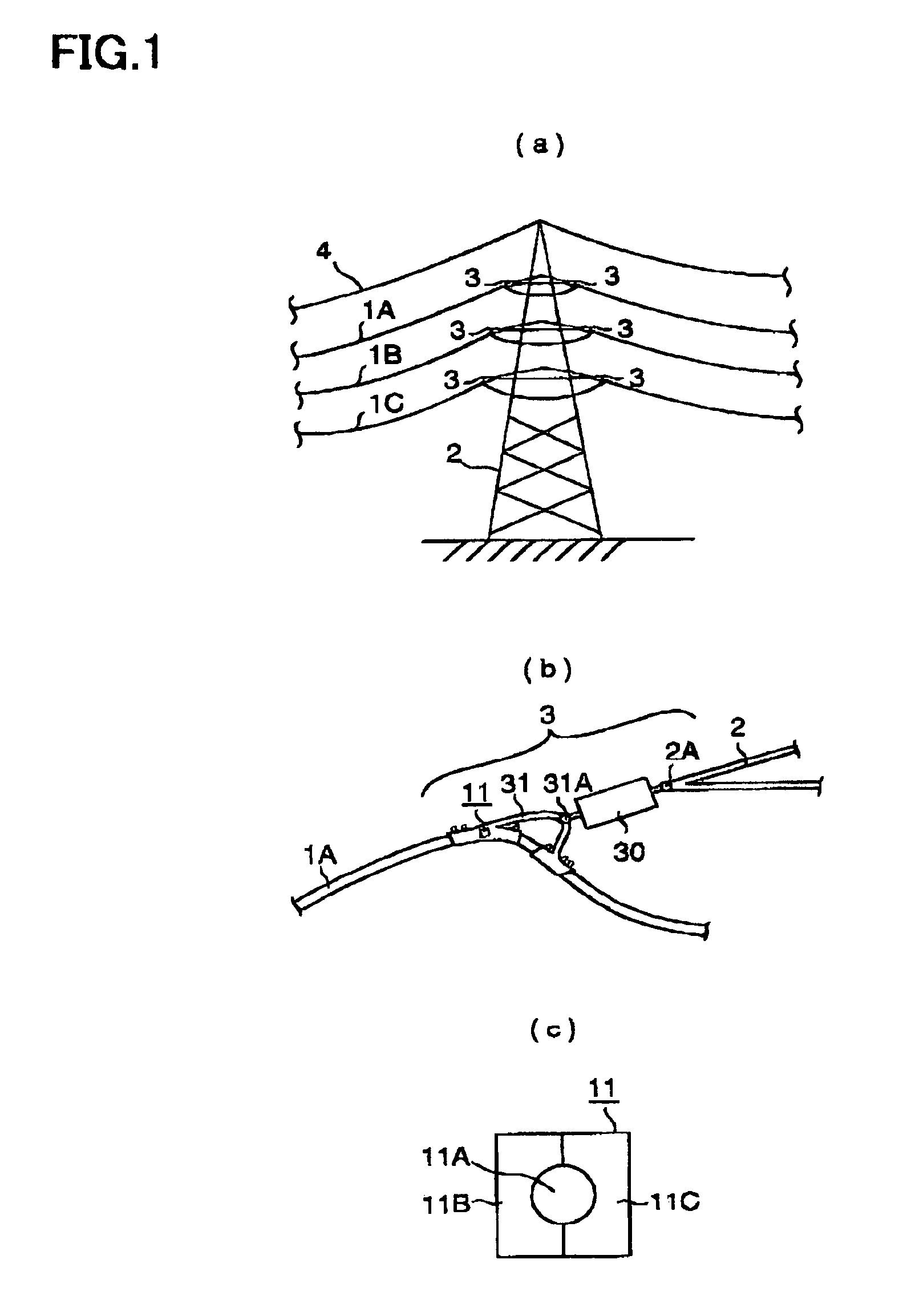
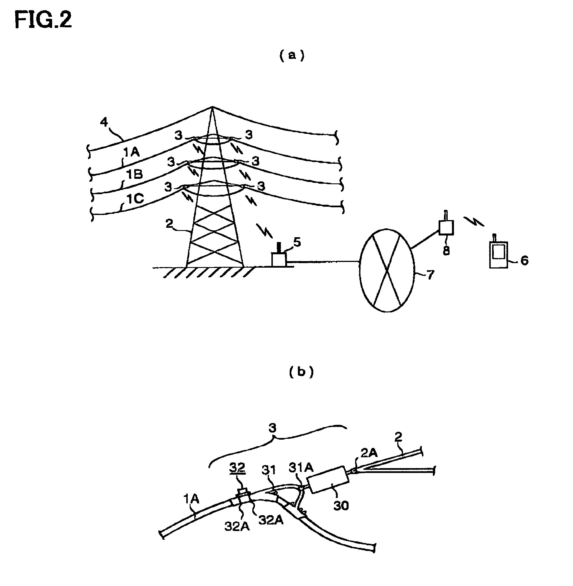
[0025]FIG. 2 shows a temperature monitoring device in a preferred embodiment of the invention, where FIG. 2(a) shows the schematic composition of a power transmission tower in which the temperature monitoring device is installed

[0026]The temperature monitoring device is composed of: a power transmission tower 2 that supports transmission lines 1A, 1B and 1C (each having two transmission lines); transmission-line supporting portions 3 provided between the power transmission tower 2 and the transmission lines 1A, 1B and 1C; an optical ground wire (OPGW) 4 provided on the top of the power transmission tower 2; a reception station 5 that receives radio wave which includes a temperature measurement data to be detected by a temperature detector (described later) for the supporting portions 3 provided on the transmission lines 1A, 1B and 1C; a portable-typ...


PUM


Abstract

Temperature measurement data obtained by measuring the temperature of a cable clamp (31) by a temperature sensor (320) is radio-transmitted from a temperature sensing unit (32) at a predetermined timing, and the radio-transmitted temperature measurement data is received by a receiving station (5), classified by the temperature sensing unit number, and stored in a temperature measurement data storage area (502A). The temperature measurement data transmitted from twelve temperature sensing units (32) can be received by one receiving station (5).

Description

[0001]The present application is based on Japanese patent application No.2001-118457, the entire contents of which are incorporated herein by reference.TECHNICAL FIELD[0002]This invention relates to a temperature monitoring device and particularly to a temperature monitoring device that can safely monitor the temperature change of a monitored object which is difficult for workers to access safely.BACKGROUND ART[0003]Conventionally, a thermo-sensing label is attached to main circuit connection of transformer station and electric power-applied section of high-voltage cable such that its color changes to indicate that a state of exceeding a predetermined temperature continues for a certain period for the purpose of constantly supplying electric power, thereby allowing the maintenance worker to visually monitor it.[0004]FIG. 1(a) shows the schematic structure of a power transmission tower 2. It is composed of the power transmission tower 2 that supports transmission lines 1A, 1B and 1C ...

Claims


Application Information

Patent Timeline
IPC IPC(8): G08C19/12G01K1/02G05B23/02
CPCG01K1/02
Inventor KAWAI, SIGEKAZUISHIKURA, TSUTOMU
Owner SANYO ELECTRIC CO LTD
Why Eureka
Try Eureka