Panoramic video system with real-time distortion-free imaging

a video system and distortion-free technology, applied in the field of panoramic video system, can solve the problems of pixel-by-pixel transformation, complex computer programs, and inability to easily interpret images by observers, and achieve the effect of minimizing software overhead and high efficiency regional transformation

Active Publication Date: 2008-02-26
PHYSICAL OPTICS CORP
View PDF3 Cites 112 Cited by
  • Summary
  • Abstract
  • Description
  • Claims
  • Application Information

AI Technical Summary

Benefits of technology

[0006]The present invention in its preferred embodiment combines a panoramic annular lens system (PAL), a unitary video camera and a PC-based software system that unwraps a 360° video image into a seamless, distortion free horizontal image image in real time. The PAL system comprises two mirrors, namely, a hyperboloidal mirror and an ellipsoidal mirror interconnected by a 360° circular refracting front or entrance aperture lens and having a rear or exit aperture adjacent a collector lens. The PAL system of the preferred embodiment has a 360° horizontal field of view and a 90° vertical field of view in a 40 mm diameter compact package. The invention is not limited to any particular type of lens system. In fact, there are numerous lens systems for providing a 360° panoramic view. The video camera may be a CCD or CMOS based device having a pixel resolution of either 1280×1024 (high resolution) or 720×480 (NTSC). The unwrapping system is a radiometric ray tracing program carried out using a computer's graphics card capabilities to produce highly efficient regional transformation while minimizing software overhead. The result is real time, high resolution 30 fps conversion from a spherical distorted image to a flat panoramic image in Cartesian coordinates. A graphic user interface (GUI) permits selection of any breaking point (any center line of the panoramic image) as well as zoom in and zoom out capability and built-in calibration.

Problems solved by technology

However, such lenses provide an image which is not readily interpretable by observers unless the image is first “unwrapped”.
The image of a 360° field of view lens is annular or doughnut-shaped and is therefore distorted and not readily discernible by a human observer.
Such pixel-by-pixel transformations are typically very complex and require complicated and time consuming computer programs, especially for reasonable levels of resolution and images having large numbers of pixels.
Consequently, it has not been possible heretofore to exploit panoramic lens technology to provide a real-time unwrapped video image with acceptable resolution.

Method used


Image

  • Panoramic video system with real-time distortion-free imaging
  • Panoramic video system with real-time distortion-free imaging
  • Panoramic video system with real-time distortion-free imaging

Examples


Embodiment Construction

Panoramic Annular Lens (PAL)

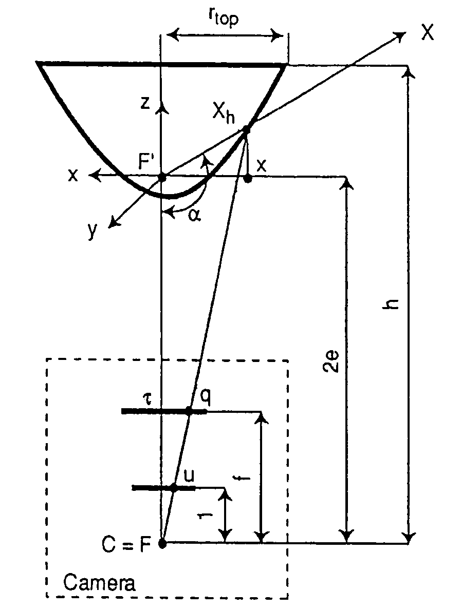
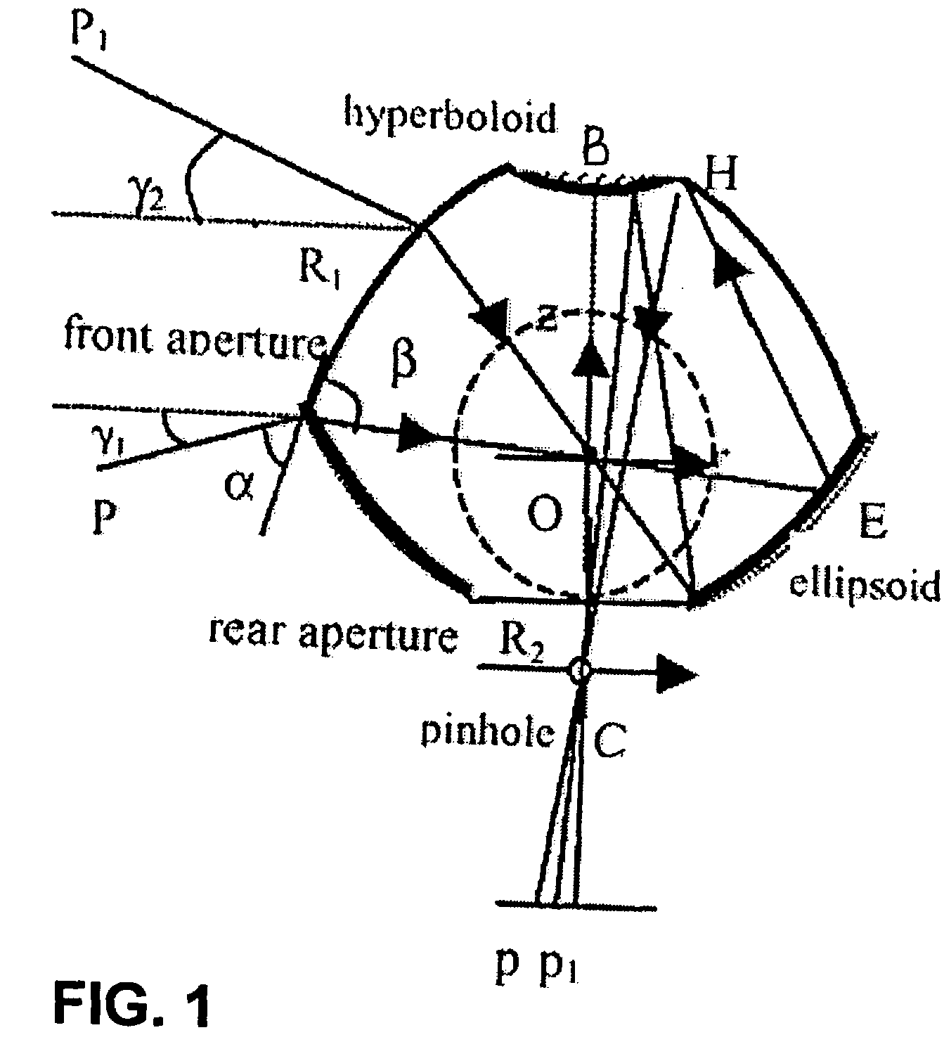
[0034]The PAL lens is based on both reflection and refraction of light and offers panoramic 360° field of view in an ultra compact packaging of only 40 mm diameter. The PAL lens provides a vertical field of view such as −40° to +50°. As shown in FIG. 1, the panoramic lens is a piece of glass that consists of a 360° circular aperture (R1), a rear aperture (R2) connecting to a collector lens, a top mirror (H) and a circular mirror (E). The viewpoint of the “virtual camera” is at the plane (O) of the ellipsoidal mirror (E). With this geometry, the PAL sensor can view the entire 360° scene around its vertical axis BC. The vertical field of view is determined by the effective sizes and the locations of the circular mirror E and the top mirror H. Usually the viewing angle is 90° vertically.

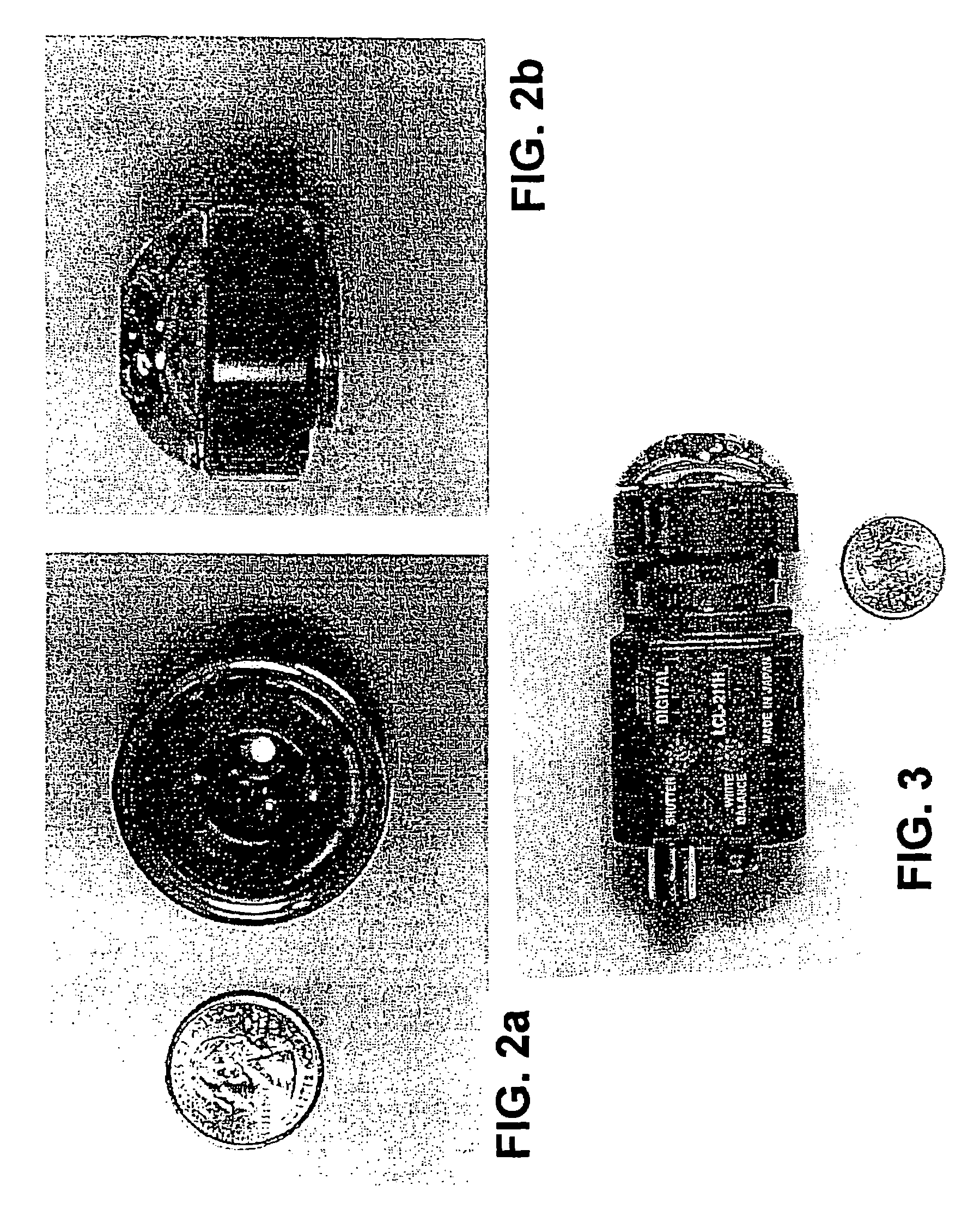
[0035]The PAL is shown in FIGS. 2a and 2b. To maintain wide camera angle options, the PAL mounting is terminated with a C-type mount that fits most ⅓ in. and ½ in. pick-up de...


PUM

PropertyMeasurementUnit
field of viewaaaaaaaaaa
diameteraaaaaaaaaa
vertical field of viewaaaaaaaaaa

Abstract

A panoramic annular lens system (PAL), a unitary video camera and a PC-based software system that unwraps a 360° video image into a seamless, distortion free horizontal image image in real time. The PAL system of the preferred embodiment has a 360° horizontal field of view and a 90° vertical field of view in a 40 mm diameter compact package. The invention is not limited to any particular type of lens system. In fact, there are numerous lens systems for providing a 360° panoramic view. The video camera may be a CCD or CMOS based device having a pixel resolution of either 1280×1024 (high resolution) or 720×480 (NTSC). The unwrapping system is a radiometric ray tracing program carried out using a computer's graphics card capabilities to produce highly efficient regional transformation while minimizing software overhead. The result is real time, high resolution 30 fps conversion from a spherical distorted image to a flat panoramic image in Cartesian coordinates.

Description

CROSS-REFERENCE TO RELATED APPLICATIONS[0001]The present invention takes priority from provisional application Ser. No. 60 / 485,336 filed on Jul. 3, 2003.ORIGIN OF THE INVENTION[0002]The invention described herein was made in the performance of work under a USMC contract No. M67854-03-C-1006, and is subject to the provisions of public law 96-517 (35 USC 202) in which the contractor has elected to retain title.FIELD OF THE INVENTION[0003]The present invention relates generally to the field of special video camera systems and more specifically to a real-time 360° panoramic video system which utilizes a panoramic annular mirror, video camera and unique unwrapping software which provides a seamless, distortion-free horizontal view of the panoramic image.BACKGROUND OF THE INVENTION[0004]Panoramic optical systems which can be employed to provide a 360° field of view, are known. By way of example, U.S. Pat. No. 6,459,451 discloses a catadioptric lens which provides a 360° field of view. Suc...

Claims


Application Information

Patent Timeline
Patent Type & Authority Patents(United States)
IPC IPC(8): H04N5/225G03C
CPCG06T3/0018G06T5/006H04N5/23238H04N23/698H04N5/262H04N5/21
Inventor KOSTRZEWSKI, ANDREW ARO, SOOKWANGAGUROK, IL'YABENNAHMIAS, MARK
Owner PHYSICAL OPTICS CORP
Why Eureka
Try Eureka