This helps you quickly interpret patents by identifying the three key elements:
Problems solved by technology
Method used
Benefits of technology
Benefits of technology
[0024]According to the present invention, the position detection can accurately be preformed even when a target mark cannot be detected by, for example, when a target mark is damaged by a wafer process.
Problems solved by technology
Even if the reproduction precision of mechanical alignment is high, variations in offset may occur due to a mechanical error in each mechanical alignment apparatus.
If the alignment mark in the above process has the same shape, it is detected by mistake, and global alignment becomes impossible.
Semiconductor manufacturing methods are recently making progress, and, in particular, planarization, which performs a polishing process called CMP is contributing to an increase in the degree of intergration, and, for this reason, a layer on the alignment mark is also polished, and a mark signal may degrade or its stability may decrease.
In flexible manufacturing, however, semiconductors are often manufactured in quantity, without optimization.
In some cases, optimization needs to be performed for each lot, which is impractical.
Even if this lot-by-lot optimization is possible, there is a limit on the number of alignment marks to be formed.
However, in this method, if the target mark is greatly damaged after having undergone a wafer process step, such as CMP, the target mark cannot be identified.
In addition, measurement resolution may be insufficient when a detection apparatus having a wide visual field for giving a higher priority to the mark identification is to perform high-precision measurement.
If the identification is possible, high-quality signals required for high-precision measurement are not always obtained.
Method used
Image
Click on the blue label to locate the original text in one second.
Reading with bidirectional positioning of images and text.
Examples
first embodiment
[0036]A reference symbol AM in FIG. 6A shows an example of an alignment mark for use in global alignment. The alignment mark AM allows simultaneous measurement in the X and Y directions in global alignment.
[0037]In global alignment, a part of the mark in a window X shown in FIG. 6A is observed by the high-magnification detection system, thereby detecting the position of the mark with a resolution higher than that in prealignment.
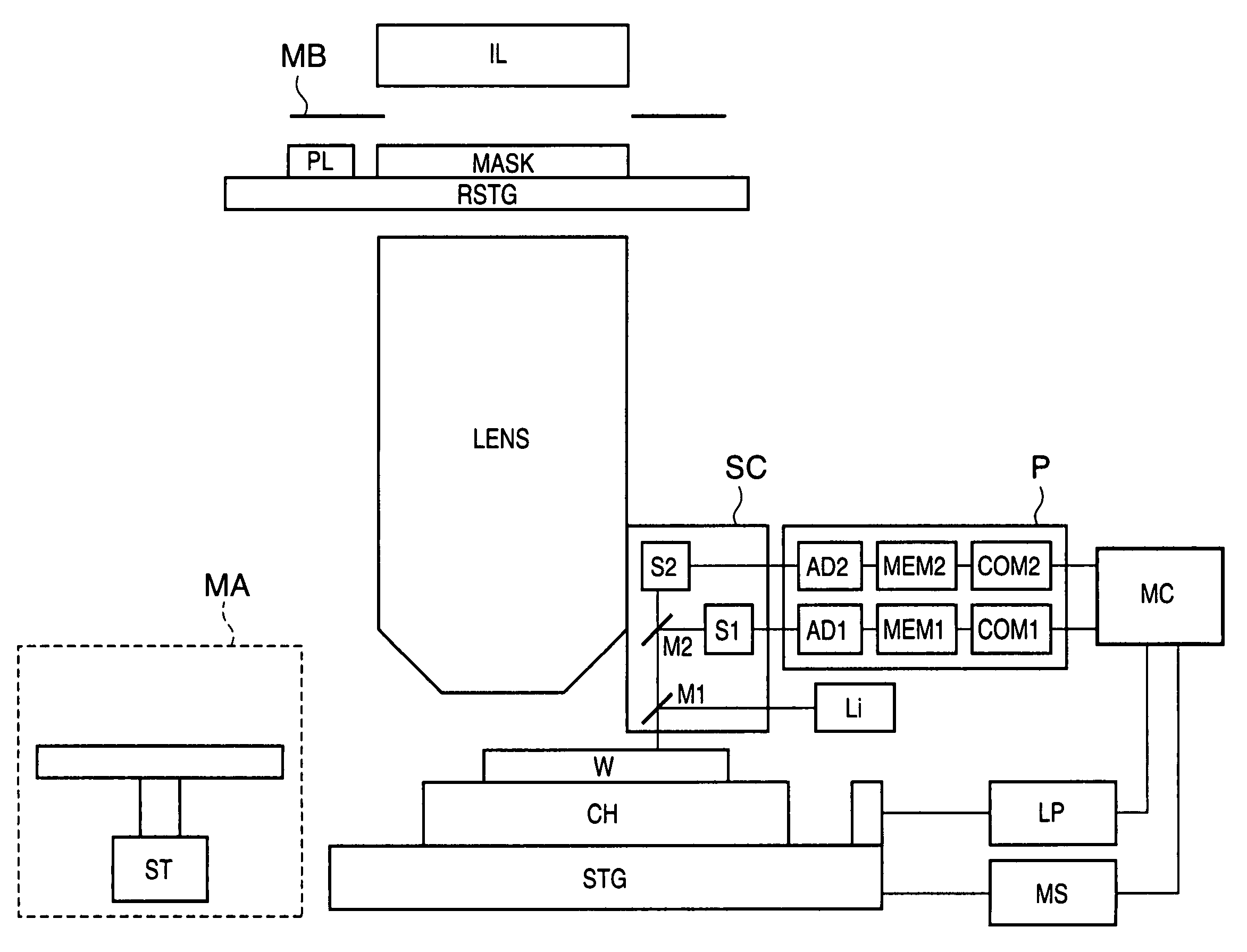
[0038]Global alignment operation will be described with reference to FIGS. 1 and 4.
[0039]When a wafer W is supplied to a semiconductor manufacturing apparatus, a mechanical alignment apparatus MA performs mechanical alignment using the circumference of the wafer W and a mark called an orientation flat or notch (N in FIG. 4) to determine the rough position of the wafer W. The wafer W is mounted on a chuck CH by a wafer supply apparatus (not shown). Global alignment is performed to obtain the accurate position of the wafer and that of an exposure shot. In glob...
second embodiment
[0069]The second embodiment will be described wherein a target mark is determined out of a plurality of similar marks in the same visual field. Note that the basic hardware arrangement, alignment marks, and measurement flow are the same as those in the first embodiment, and a detailed description thereof will be omitted. Only the differences will be described.
[0070]If a target mark P1 falls outside a visual field, as shown in FIG. 3A, mark detection is generally impossible. Similar marks other than the mark P1 fall within the visual field. If the positional relationship between P1 and each of marks L1, M1, N1, and O1 is stored in advance, any of the marks L1, M1, N1, and O1 is changed to a new target mark. At this time, shift amounts dx and dy for fine measurement are calculated on the basis of the position of the target mark selected out of the detectable marks. For example, assume that the mark L1 can be detected. The mark L1 is changed to the new alignment mark, and amounts dx an...
third embodiment
[0072]The third embodiment will be described wherein a target mark is determined out of a plurality of similar marks in the same visual filed. The first and second embodiments explain a method of adding auxiliary patterns and discriminating marks using the auxiliary patterns. The third embodiment will describe a method of determining, without any auxiliary patterns, a target mark out of a plurality of patterns having similar shapes in a visual field. Note that the basic hardware arrangement, alignment marks, and measurement flow are the same as those in the first embodiment, and a detailed description thereof will be omitted. Only the differences will be described.
[0073]As shown in FIG. 3C, a target mark P1 falls outside the visual field, and similar marks other than the mark P1 fall within the visual field. The target mark P1 is separated from the marks by different spacings. Spacings SPX1, SPX2, SPY1, and SPY2 are different from each other. All the marks are arranged such that the...
PUM
Abstract
An apparatus for detecting a position of a target mark out of a plurality of marks in a region of an object to obtain a position of the region of the object. The apparatus includes a scope configured to sense a first image of the object at a first magnification and a second image of the object at a second magnification higher than the first magnification, and a processor configured to extract, from the first image, a position of a first mark out of the plurality of marks and a feature of a region outside the first mark, to identify the first mark based on the extracted feature, to extract, from the second image, a position of the target mark, to evaluate reliability of the extracted position of the target mark, to select a second mark, different from the target mark, from the plurality of marks as a new target mark based on the evaluated reliability and the identified first mark in order to extract a position of the selected second mark from an image sensed by the scope at the second magnification.
Description
FIELD OF THE INVENTION[0001]The present invention relates to a technique for detecting a position of a target mark included in an object.BACKGROUND OF THE INVENTION[0002]Wafer alignment in a conventional semiconductor manufacturing apparatus will be described with reference to FIGS. 1, 4, 6A to 6C, and 7.[0003]When a wafer W is supplied to the semiconductor manufacturing apparatus, a mechanical alignment apparatus MA performs mechanical alignment using the circumference of the wafer W and a mark called an orientation flat or a notch (N in FIG. 4) to determine the rough position of the wafer W. The precision of the mechanical alignment is about 20 μm. The wafer W is mounted on a chuck CH by a wafer supply apparatus (not shown) to perform global alignment. In global alignment, measurement marks FXY1 to FXY4 shown in FIG. 4 are measured, thereby obtaining shifts in the X and Y directions, a rotational component, and a magnification component of the shot array. The precision of the glob...
Claims
Application Information
Patent Timeline
Application Date:The date an application was filed.
Publication Date:The date a patent or application was officially published.
First Publication Date:The earliest publication date of a patent with the same application number.
Issue Date:Publication date of the patent grant document.
PCT Entry Date:The Entry date of PCT National Phase.
Estimated Expiry Date:The statutory expiry date of a patent right according to the Patent Law, and it is the longest term of protection that the patent right can achieve without the termination of the patent right due to other reasons(Term extension factor has been taken into account ).
Invalid Date:Actual expiry date is based on effective date or publication date of legal transaction data of invalid patent.

