

Imaging polarimetry
a polarimetry and polarimetry technology, applied in the field of polarimetry, can solve the problems of limited degree of size reduction, high cost, and high cost, and achieve the effect of reducing measurement errors
- Summary
- Abstract
- Description
- Claims
- Application Information
AI Technical Summary
Benefits of technology
Problems solved by technology
Method used
Image

Examples
example 2
[0318]The relation between the Δφ1(x, y) and Δφ2(x, y) is found by applying fluctuation (temperature change, for example) actually.
3.2.3 Actual Calibration Method
[0319]The basic idea on the calibration method is completely the same as in Section 3. 1. There thus exist calculation methods corresponding to all A to E described in Section 3. 1. 3. Hence, in this section, the idea is described only when different from that of the previous section, and the following description concentrates on listing of mathematical expressions.
[0320]First, a couple of symbols are defined. The reference phase functions obtained by the pre-calibration are defined as φ1(i)(x, y) and φ2(i)(x, y). Reference complex functions corresponding to these reference phase functions are expressed as follows according to Expressions (1.18a) to (1.18d).
[0321][MathematicalExpression36]K0(i)(x,y)=12m0(x,y)(3.19a)K-(i)(x,y)=18m-(x,y)expⅈ[ϕ2(i)(x,y)-ϕ1(i)(x,y)](3.19b)K2(i)(x,y)=14m2(x,y)expⅈϕ2(i)(...
example 1
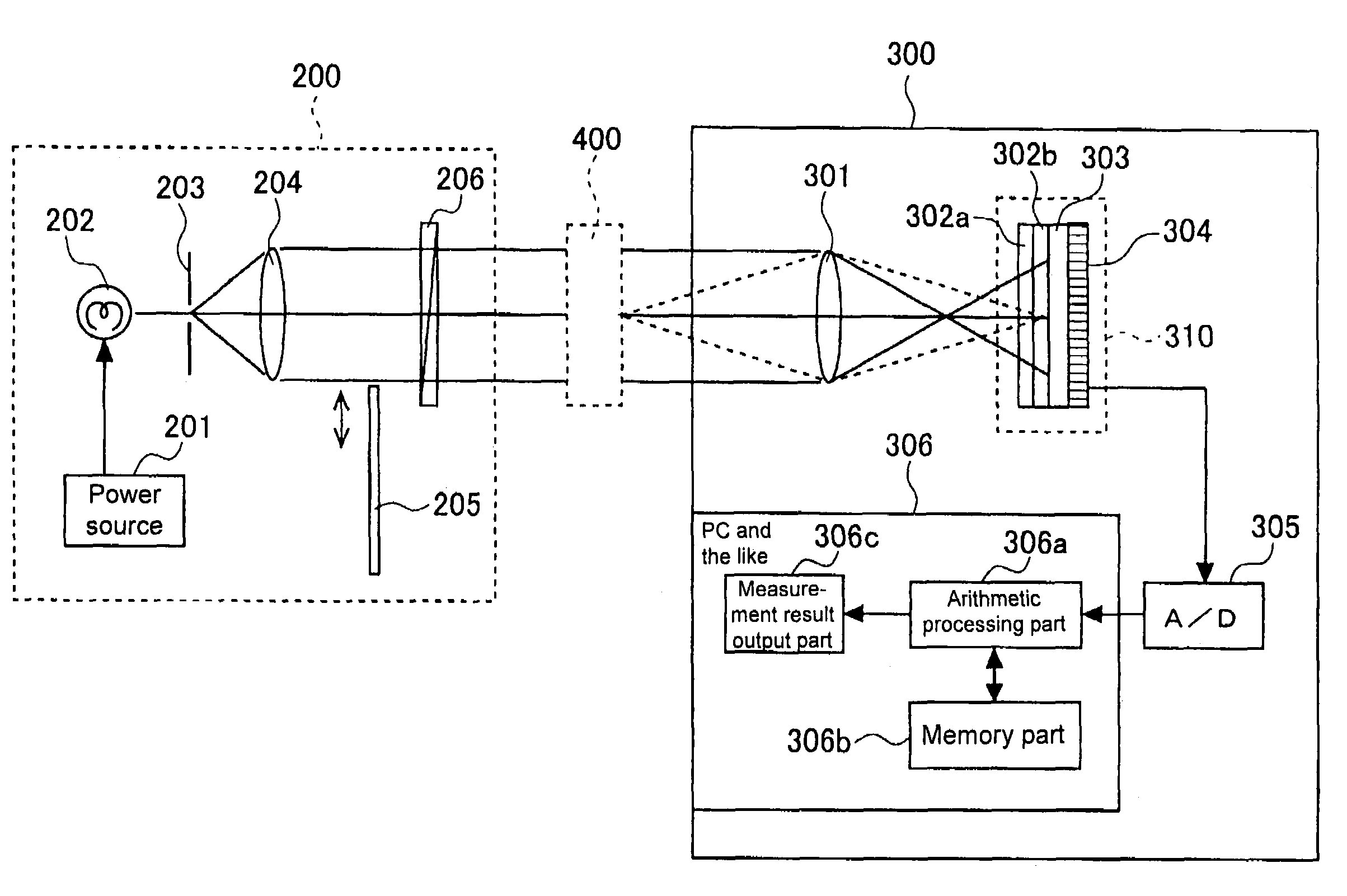
[0410]In the following, a preferred example of the present invention is specifically described with reference to FIGS. 12 to 18. FIG. 12 shows a constitutional view of one example of an imaging polarimeter. As shown in this figure, this device comprises a photo-projecting side unit 200 and a photo-receiving side unit 300. It is to be noted that numeral 400 denotes a sample.
[0411]The photo-projecting side unit 200 comprises: a power source 201; a light source 202 that is turned on by power feeding from the power source 201; a pinhole plate 203 arranged on the front face side of the light source 202 in the light-projecting direction; a collimator lens 204 for collimating light transmitting through the pinhole of the pinhole plate 203; a shutter 205 which is arranged on the front face side of the collimator lens 204 and opens and closes to transmit or block the transmitted light; and a polarizer 206 on which the light having transmitted through the shutter is incident.
[0412]The light a...
PUM
 Abstract
Description
Claims
Application Information