
Tactile user interface with application-specific tactile behavior

a user interface and tactile technology, applied in the field of computer interfaces, can solve the problems of inability to provide an optimal, more complex and expensive system that employs multi-dimensional or proportional feedback, and has not been widely adopted to provide an optimal. , to achieve the effect of providing meaningful tactile feedback, simple and inexpensive tactile pointing devices, and supplementing visual navigation

Inactive Publication Date: 2008-02-26
ELBING KRISTOFER E +1
View PDF17 Cites 13 Cited by
  • Summary
  • Abstract
  • Description
  • Claims
  • Application Information

AI Technical Summary

Benefits of technology

[0009]The invention is advantageous in that it can provide a user with meaningful tactile feedback from a general-purpose computer with a simple and inexpensive tactile pointing device. By sending change-of region signals to a pointing device, embodiments of the invention provide information to the user when he or she needs it most—when the pointing device is being manipulated. Systems according to the invention can also be advantageous in that they permit multiple modes of interacting with the computer, depending both on whether a system can identify an application the user is interacting with and the type of that application.
[0010]Tactile sensation according to the invention can benefit a computer user by supplementing visual navigation. This additional information may increase productivity, reduce errors, or both. These enhancements can be particularly important in detailed authoring tasks, or where there is a large amount of confusing information on the screen, such as in the case of a multi-tasking operating system with several windows open.

Problems solved by technology

More complex and expensive systems that employ multi-dimensional or proportional feedback have also been proposed.
None of the prior art approaches, however, has been widely adopted to provide an optimum general-purpose pointing device with tactile feedback for use with graphical user interfaces.

Method used


Image

  • Tactile user interface with application-specific tactile behavior
  • Tactile user interface with application-specific tactile behavior
  • Tactile user interface with application-specific tactile behavior

Examples


Embodiment Construction

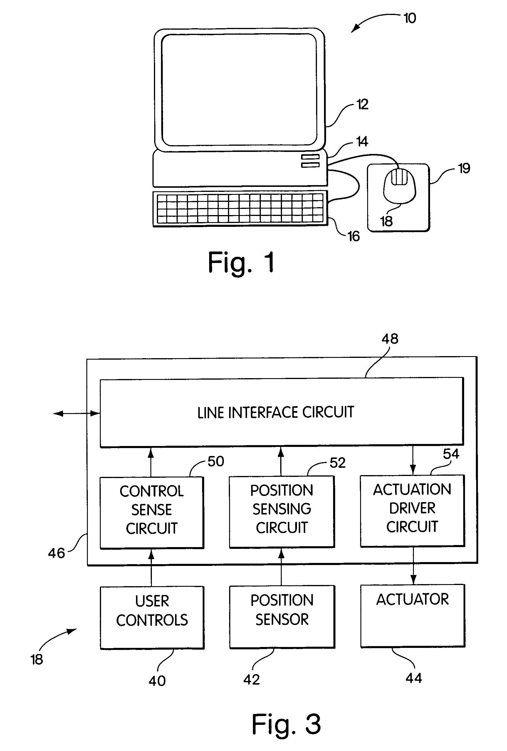
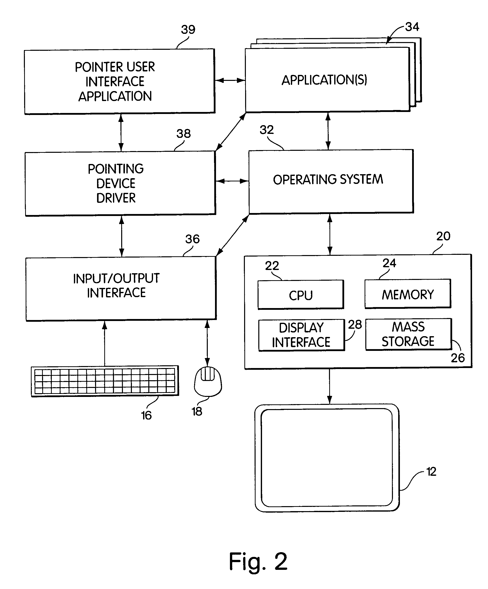
[0024]Referring to FIGS. 1 and 2, an illustrative computer system 10 according to one general aspect of the invention includes a display 12, a processing system 14, a keyboard 16, and an interactive pointing device 18, which can be a mouse. The processing system includes processing circuitry 20 that comprises computing circuitry components such as a central processing unit 22, memory storage 24, mass storage 28 (e.g., disk storage), and display interface circuitry 28 to provide display signals to the display. The display interface circuitry can take the form of a special-purpose display processor.

[0025]Also included in the processing system 14 is an operating system 32 that interacts with the processing circuitry 20. The operating system provides system support functions that enhance the capabilities of the processing circuitry, such as a file system, task management, and drivers. The operating system can also provide menu support and windowing capabilities.

[0026]An input / output int...


PUM


Abstract

A computer system includes a computer processor, an operating system operative in connection with the computer processor, and a display responsive to the operating system. The system also has a pointing device that includes a position sensor and a tactile actuator. A pointing device driver is responsive to the position sensor, and the tactile actuator is responsive to the pointing device driver. A general-purpose application is responsive to the pointing device driver and to the operating system and in communication with the display, and the pointing device driver is also responsive to the general purpose application. The system further includes a profile that maps region changes associated with material displayed on the screen to tactile signals to be sent to the tactile actuator.

Description

[0001]This application is a continuation of Ser. No. 09 / 028,069, filed Feb. 23, 1998 now U.S. Pat. No. 6,219,034, which is herein incorporated by reference.FIELD OF THE INVENTION[0002]This invention relates to computer interfaces that employ tactile feedback.BACKGROUND OF THE INVENTION[0003]General-purpose pointing devices, such as the well-known mouse, have been widely adopted as a supplement to keyboards in the user interfaces of computers. One type of prior art mouse has been equipped with a tactile feedback area to provide a virtual graphic display to blind users. Another features an actuator that provides a variable resistance to motion of the mouse. More complex and expensive systems that employ multi-dimensional or proportional feedback have also been proposed. None of the prior art approaches, however, has been widely adopted to provide an optimum general-purpose pointing device with tactile feedback for use with graphical user interfaces.SUMMARY OF THE INVENTION[0004]In one...

Claims


Application Information

Patent Timeline
IPC IPC(8): G09G5/00G06K3/00G06F3/00G06F3/01G06F3/0354
CPCG06F3/016G06F3/03543G06F2203/014G06F3/0488
Inventor ELBING, KRISTOFER E.FOOTE, JONATHAN T.
Owner ELBING KRISTOFER E
Learn More