
Distribution assembly for particulate material

a technology of particulate material and assembly, which is applied in the direction of loading/unloading vehicles, transportation items, and ways, can solve the problems of slow discharge rate and proportionately less material delivery, and achieve the effect of reducing size and speeding up the distribution speed

Inactive Publication Date: 2008-03-04
BLATT MICHAEL S
View PDF15 Cites 9 Cited by
  • Summary
  • Abstract
  • Description
  • Claims
  • Application Information

AI Technical Summary

Benefits of technology

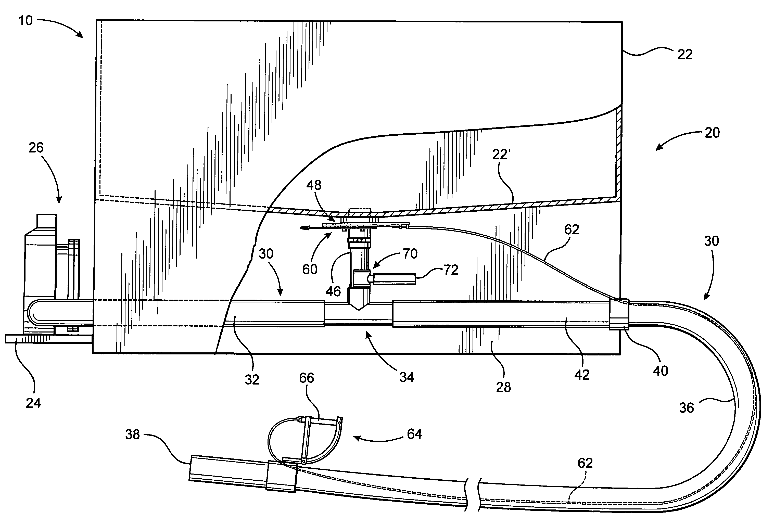
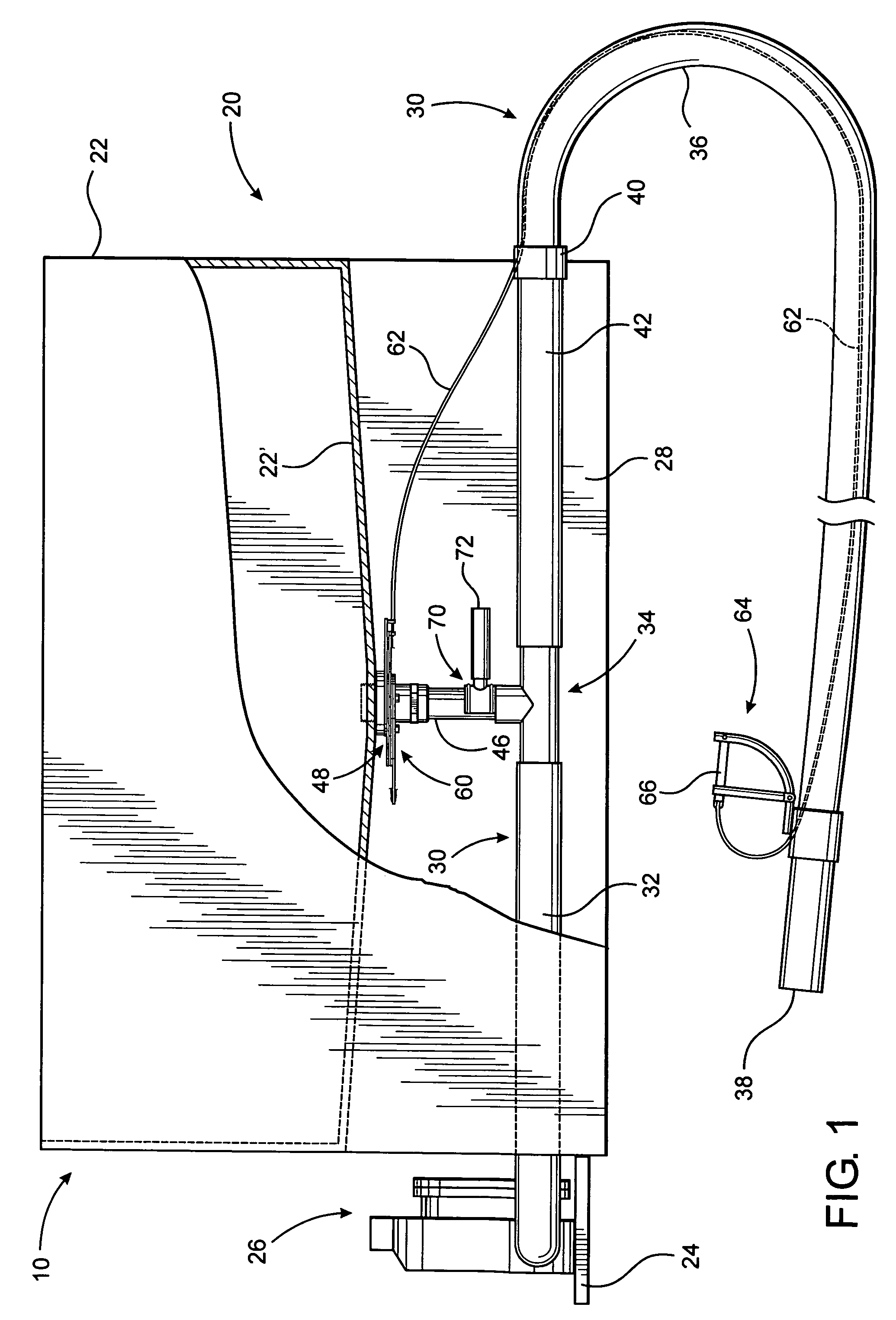
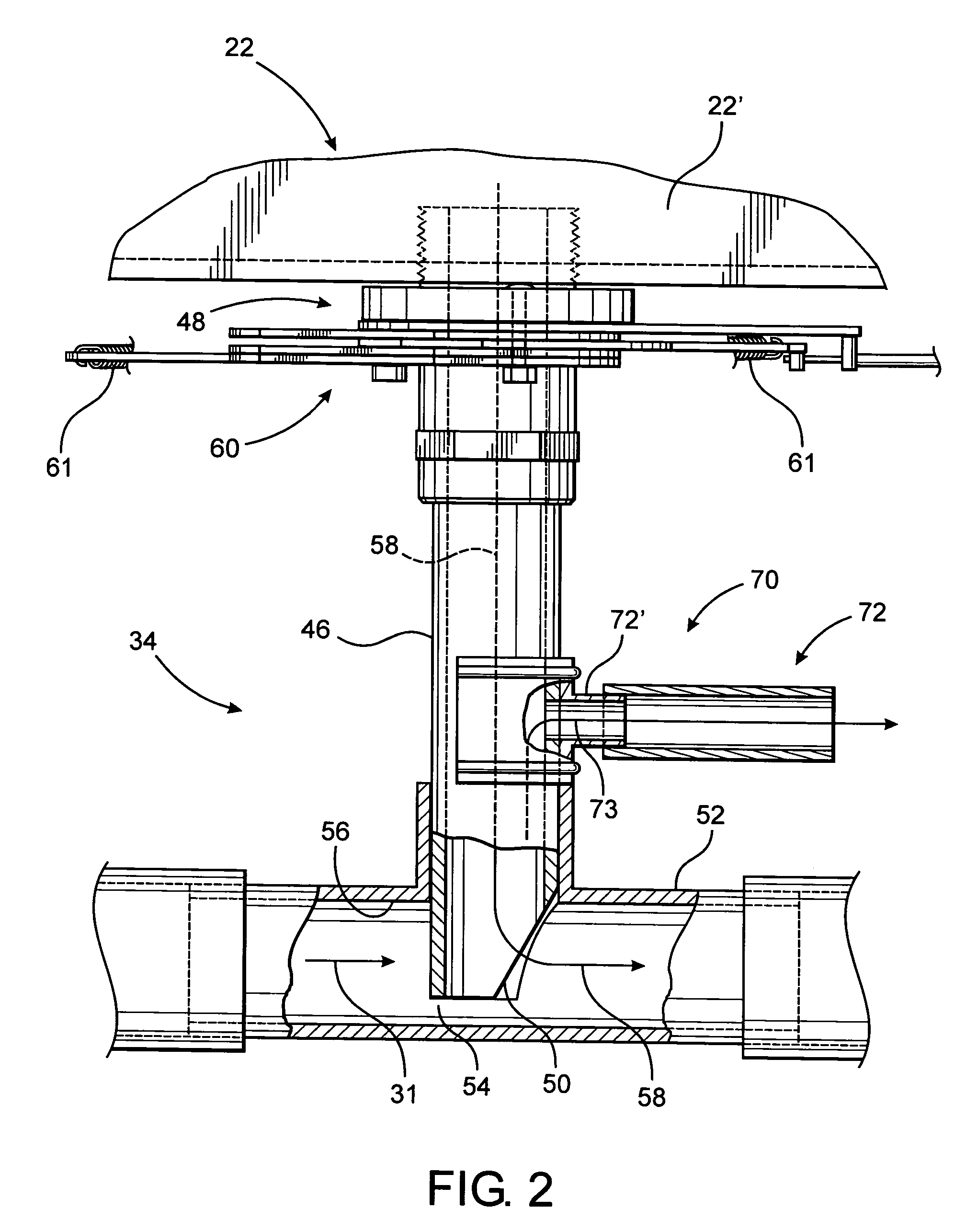
[0013]The present invention is directed to an assembly structured to rapidly and efficiently distribute a variety of different particulate materials such as, but not limited to, fertilizers, herbicides and the like by utilizing a blower assembly in combination with a uniquely structured manifold assembly. As such, the distribution assembly of the present invention overcomes many, if not all, of the disadvantages and problems associated with conventional or known particulate spreaders. In doing so, the distribution assembly may be used independently of or be mounted on any of a variety of different mobile platforms including wheeled vehicles or structures which are motorized or manually powered, as well as various types of marine craft. Accordingly, depending on the specific application, the distribution assembly of the present invention can be utilized to disperse particulate materials of various types and sizes over an extended ground surface, throughout a water environment and / or directly to smaller, substantially predetermined area of reduced sizes, spaces or locations, such as to potted plants.

Problems solved by technology

Moreover, when treating significantly smaller and / or generally predetermined area of reduced sizes such as, but not limited to, potted plants, more precise applications are required resulting in a slower discharge rate and the delivery of proportionately less material, over a given period of time.

Method used


Image

  • Distribution assembly for particulate material
  • Distribution assembly for particulate material
  • Distribution assembly for particulate material

Examples


Embodiment Construction

[0063]As shown in the accompanying Figures, the present invention is directed to a distribution assembly, generally indicated as 10 in FIG. 1, which is structured to distribute a wide variety of particulate materials such as, but not limited to, fertilizer and the like. As will be further evident from the following description of the one or more preferred embodiments of the present invention, the distribution assembly 10 may be mounted on any of a variety of different mobile platforms.

[0064]By way of example, such mobile platforms may include, but are not limited to, a manually powered spreader assembly generally indicated as 12 in FIG. 3 or a truck or other motorized vehicle generally indicated as 80 in FIG. 4. The adaptation of the distribution assembly of the present invention, including the various preferred embodiments thereof, will be described in greater detail hereinafter with primary references to the appropriate figures. In addition to the embodiments of FIGS. 3 and 4, the...


PUM


Abstract

An assembly for distributing particulate material comprising a blower assembly preferably removably mounted on a mobile platform and structured to generate a forced flow of air along a flow path and through a manifold assembly connected to a supply of material being distributed. The manifold assembly includes a receiving segment incorporating a Venturi section facilitating the introduction of the particulate material into the forced air flow passing through a discharge conduit. The discharge conduit preferably has an extended length to facilitate distribution of the material to a plurality of locations in a variety of different environments. An applicator is selectively attached to the discharge conduit so as to facilitate distribution of the particulate material to a substantially confined space, such as a potted plant.

Description

CLAIM OF PRIORITY[0001]The present application is a continuation application of previously filed, now pending application, having Ser. No. 10 / 793,655, filed on Mar. 3, 2004 which is to mature into U.S. Pat. No. 7,137,579, which was a continuation-in-part application of then application, having Ser. No. 10 / 227,729, filed on Aug. 26, 2002 now U.S. Pat. No. 6,883,736, which are included herein in their entirety by reference.BACKGROUND OF THE INVENTION[0002]1. Field of the Invention[0003]This invention relates to an assembly for distributing fertilizer, as well as a large variety of other particulate materials, which is adaptable to be mounted on different types of ground or water traveling vehicles. The distribution assembly is structured to regulate the introduction of the particulate material into an air flow thereby facilitating the distribution of the material throughout large and / or hard to reach areas as well as smaller, substantially confined areas.[0004]2. Description of the Re...

Claims


Application Information

Patent Timeline
IPC IPC(8): A01C15/04B05B7/14B60P1/60B65G53/40E01C19/20
CPCA01C15/04B60P3/30B65G53/10B65G53/14
Inventor BLATT, MICHAEL S.
Owner BLATT MICHAEL S
Learn More