Apparatus and method for controlling a power converter device
a power converter and control device technology, applied in the direction of power conversion systems, dc-dc conversion, instruments, etc., can solve the problems of sensitivity of current control devices to switching noise, unstable peak current control devices, and inability to control peak current, so as to achieve little or no sub-harmonic oscillation and immunity to noise
- Summary
- Abstract
- Description
- Claims
- Application Information
AI Technical Summary
Benefits of technology
Problems solved by technology
Method used
Image

Examples
first embodiment
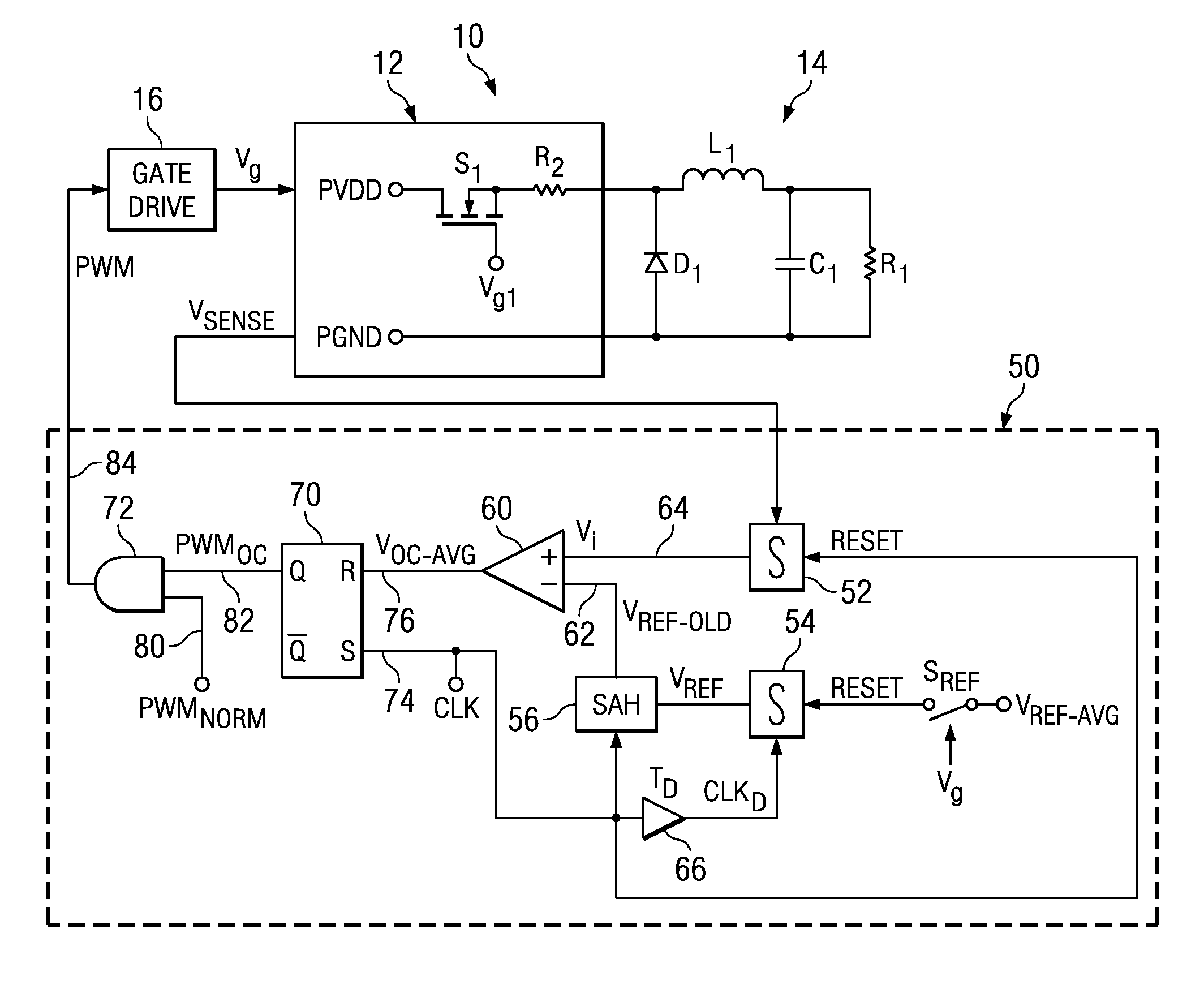
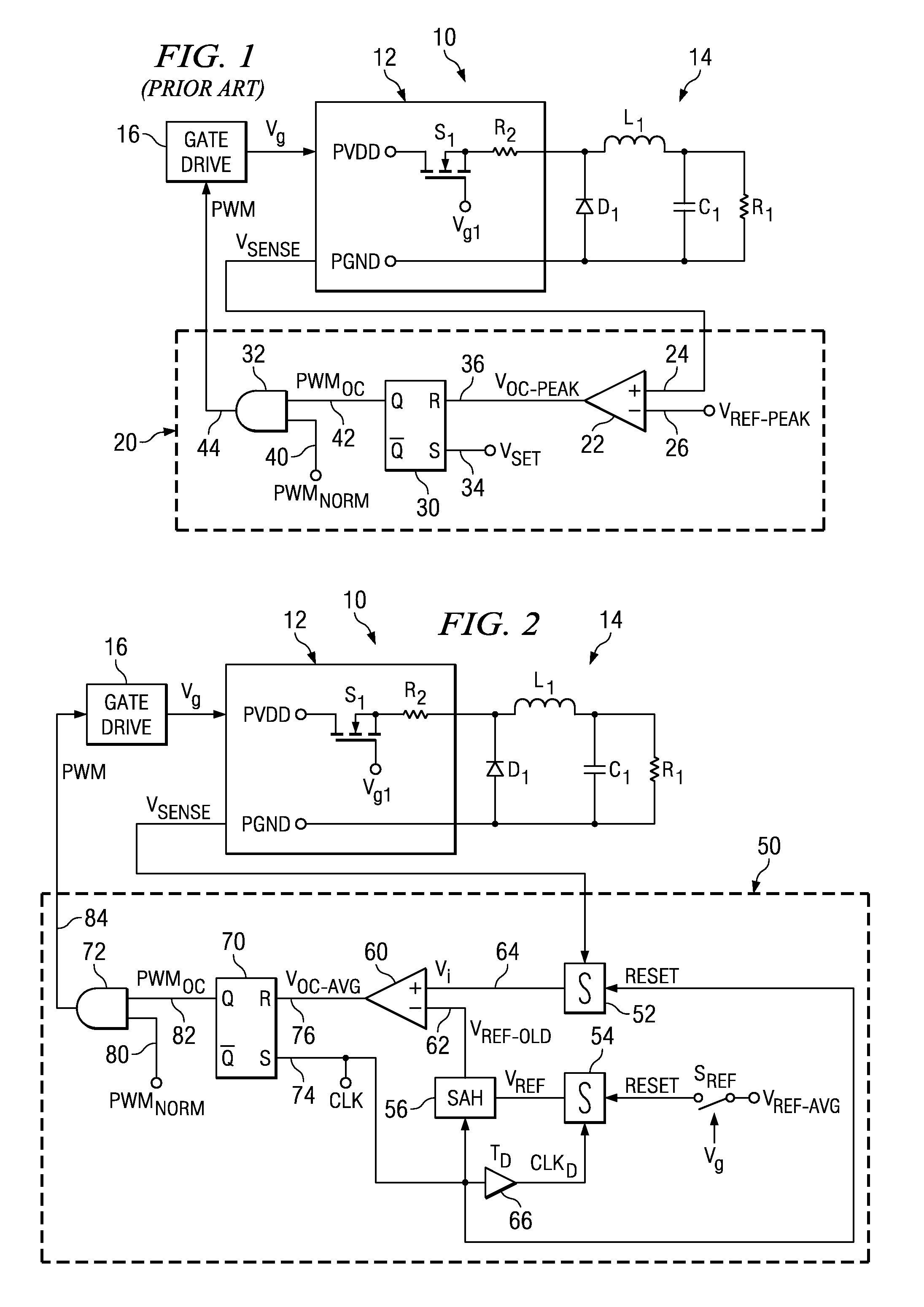
[0026]FIG. 2 is an electrical schematic diagram of a representative switching power converter device with a current limit control apparatus configured according to the present invention. In FIG. 2, a power converter device 10 is configured substantially as illustrated and described in connection with FIG. 1. In the interest of avoiding prolixity, the description of power converter device 10 will not be repeated here.
[0027]An adaptive cycle-by-cycle average current control unit 50 is coupled to receive sensed signal VSENSE. Current control unit 50 includes a first integrator unit 52 and a second integrator unit 54. First integrator unit 52 receives sensed signal VSENSE. Second integrator unit 54 receives an average signal reference signal VREF-AVG via a switch SREF. Switch SREF is controlled by gating signal Vg. Second integrator unit 54 integrates reference signal VREF-AVG with respect to time to present an integrated reference signal VREF to a sample-and-hold (SAH) circuit 56. SAH ...
second embodiment
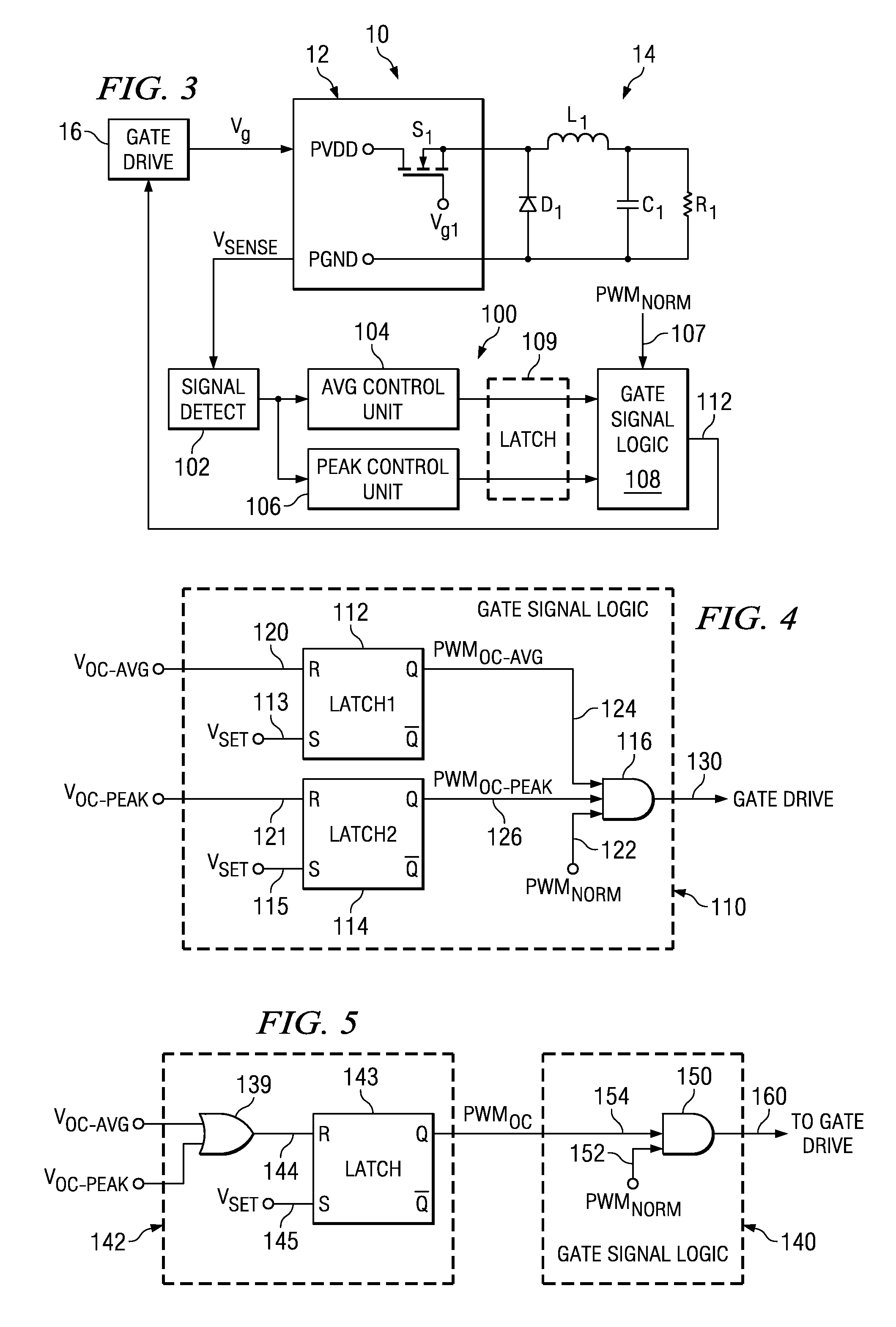
[0034]FIG. 3 is an electrical schematic diagram of a representative switching power converter device with a current limit control apparatus configured according to the present invention. In FIG. 3, a power converter device 10 is configured substantially as illustrated and described in connection with FIG. 1. In the interest of avoiding prolixity, the description of power converter device 10 will not be repeated here.
[0035]A combined current control unit 100 is coupled to receive sensed signal VSENSE. Combined current control unit 100 includes a signal detect unit 102, an average current control unit 104, a peak current control unit 106 and gate signal logic unit 108. Signal detect unit 102 is preferably embodied to cooperate with average current control unit 104 to effect control of power converter device 10 substantially as control is effected by current control unit 50 an as described in connection with FIG. 2. Signal detect unit 102 is preferably further embodied to cooperate wit...
third embodiment
[0049]FIG. 6 is an electrical schematic diagram of a current limit control apparatus configured according to the present invention. In FIG. 6, a comparing circuit 170 receives sensed signal VSENSE at a first input locus 172. An average reference signal −VREF-AVG is received at a second input locus 174. Signal −VREF-AVG is preferably substantially equal in magnitude to VREF-AVG of FIG. 2 and controls the target average current limit threshold. A common voltage VCOM is a received at a third input locus 176. Voltage VCOM may be electrical ground in some applications of comparing circuit 170.
[0050]Phase-responsive switches 180, 190, 200 respond to phase signals provided by a phase driver (not shown in FIG. 6) applying a phase signal to a phase input locus 178. Phase signals impose odd and even phases during alternate switching cycles established by a PWM signal such as PWM signal PWMNORM (FIGS. 1-5), or a clock signal CLK such as at locus 74 of FIG. 2. Phase-responsive switch 180 respon...
PUM
 Abstract
Description
Claims
Application Information
 - R&D
- Intellectual Property
- Life Sciences
- Materials
- Tech Scout
- Unparalleled Data Quality
- Higher Quality Content
- 60% Fewer Hallucinations
Browse by: Latest US Patents, China's latest patents, Technical Efficacy Thesaurus, Application Domain, Technology Topic, Popular Technical Reports.
© 2025 PatSnap. All rights reserved.Legal|Privacy policy|Modern Slavery Act Transparency Statement|Sitemap|About US| Contact US: help@patsnap.com