Ultra-broadband antenna system combining an asymmetrical dipole and a biconical dipole to form a monopole

a technology of monopoly and dipole, applied in the direction of resonant antennas, separate antenna unit combinations, elongated active elements, etc., can solve the problems of less desirable gain characteristics of narrow-band antennas, device occupying more space at the point of attachment, and limiting the usefulness of narrow-band antennas to a relatively narrow band of frequencies. , to achieve the effect of minimizing inferen

Active Publication Date: 2008-03-04
FIRST RF CORP
View PDF26 Cites 39 Cited by
  • Summary
  • Abstract
  • Description
  • Claims
  • Application Information

AI Technical Summary

Benefits of technology

[0023]The combination may further comprise a canister sub-assembly, attached to the asymmetrical dipole antenna, that provides frequency adjustment for the monopole antenna; a choke sub-assembly, provided within the canister sub-assembly, that minimizes inference between the asymmetrical dipole antenna, the biconical dipole antenna and the monopole antenna; a balun sub-assembly, provided within the asymmetrical dipole antenna, that feeds current to the asymmetrical dipole antenna and the biconical dipole antenna together via a first RF connection; a base sub-assembly, attached to the canister sub-assembly, that attaches the system to a substrate and provides a conductive path for ground return currents of the monopole antenna; and a second RF connection that feeds current to the monopole antenna.
[0030]The method of the present invention may further comprise the steps of providing a canister sub-assembly for frequency adjustment of the monopole antenna; providing a choke sub-assembly for minimizing inference between the asymmetrical dipole antenna, the biconical dipole antenna and the monopole antenna; providing a balun sub-assembly for feeding current to the asymmetrical dipole antenna and the biconical dipole antenna together via a first RF connection; and providing a base sub-assembly for attaching the system to a substrate and providing a conductive path for ground return currents of the monopole antenna; providing a second RF connection for feeding current to the monopole antenna; providing a cylinder expander ring for insulating the asymmetrical dipole element and the biconical dipole element electrically from the monopole antenna;. and providing a dielectric isolator for insulating the base sub-assembly from the monopole antenna.

Problems solved by technology

Typically, these antennas are intended to transmit and receive signals having frequencies within a defined range, and the dimensions and geometry of a particular antenna limit its usefulness to a relatively narrow band of frequencies.
Broadband antennas, or those capable at operating at more than one range of frequencies, are well known, but typically have less desirable gain characteristics than narrow-band antennas.
A drawback to the multiple-antenna approach, however, is that such a device takes up more space at its point of attachment and may be more complicated and fragile than single antenna designs.
This may not be acceptable, for example, in mobile applications.
A problem with both of these approaches is that as the frequency range expands, the antenna dimensions become increasingly large in diameter.
For certain applications, an excessively large diameter antenna is impractical or even impossible.
This becomes a major handicap for tunable antennas, however, when the frequency of operation of the system is not known.
The “frequency plan” for hopping is not always known ahead of time, which can hinder the ability of a frequency tunable antenna in receive mode to be used in hopping systems.
In general, it is inconvenient and unreliable to make manual adjustments every time a frequency change is needed.
A drawback of such a tunable antenna, however, is the complexity and cost of active components that are required for the adjustable tuning.

Method used


Image

  • Ultra-broadband antenna system combining an asymmetrical dipole and a biconical dipole to form a monopole
  • Ultra-broadband antenna system combining an asymmetrical dipole and a biconical dipole to form a monopole
  • Ultra-broadband antenna system combining an asymmetrical dipole and a biconical dipole to form a monopole

Examples


Embodiment Construction

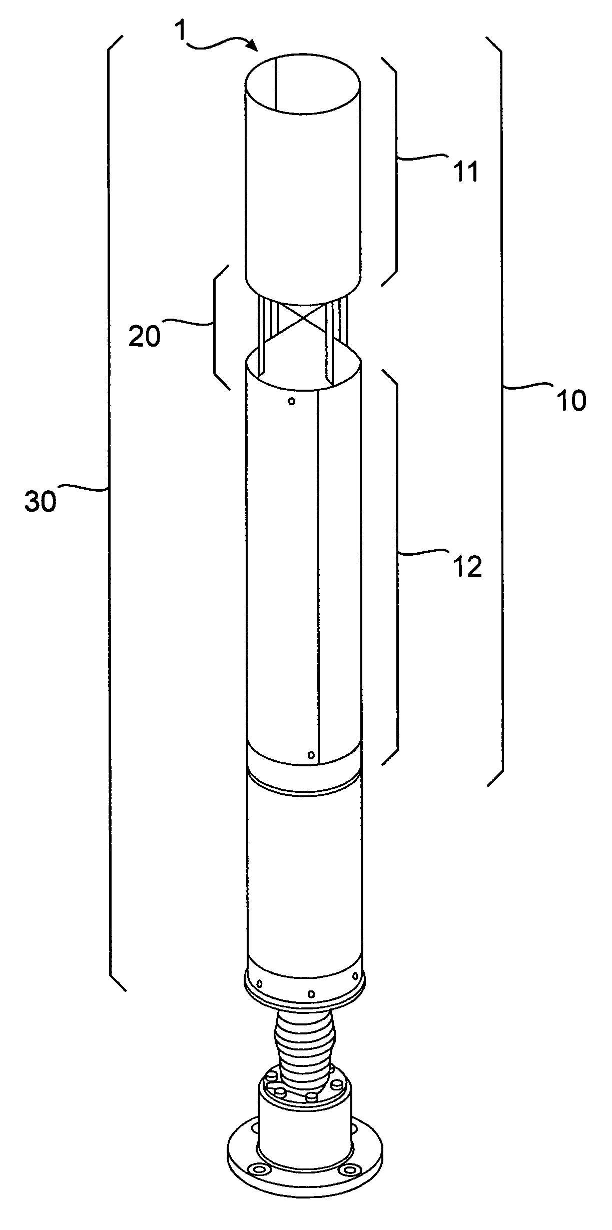
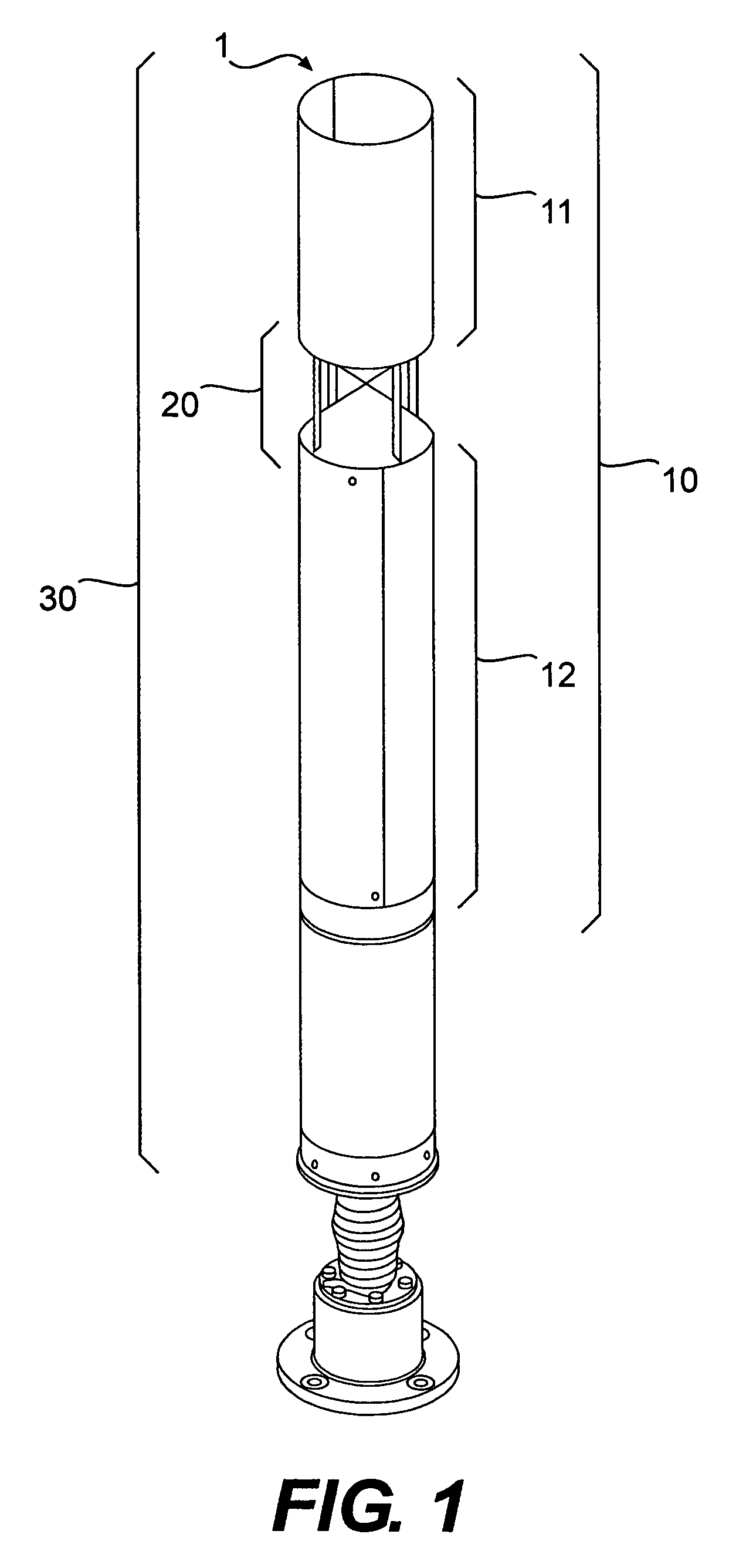
[0063]Referring now to FIG. 1, a preferred embodiment of the present invention is shown as ultra-broadband antenna system 1. Ultra-broadband antenna system 1 preferably comprises asymmetrical dipole element 10 and biconical dipole element 20, which together combine to form monopole element 30. Asymmetrical dipole element 10 further comprises upper asymmetrical dipole element 11 and lower asymmetrical dipole element 12. FIG. 1 diagrams the functionality of components of the ultra-broadband antenna system of the present invention.

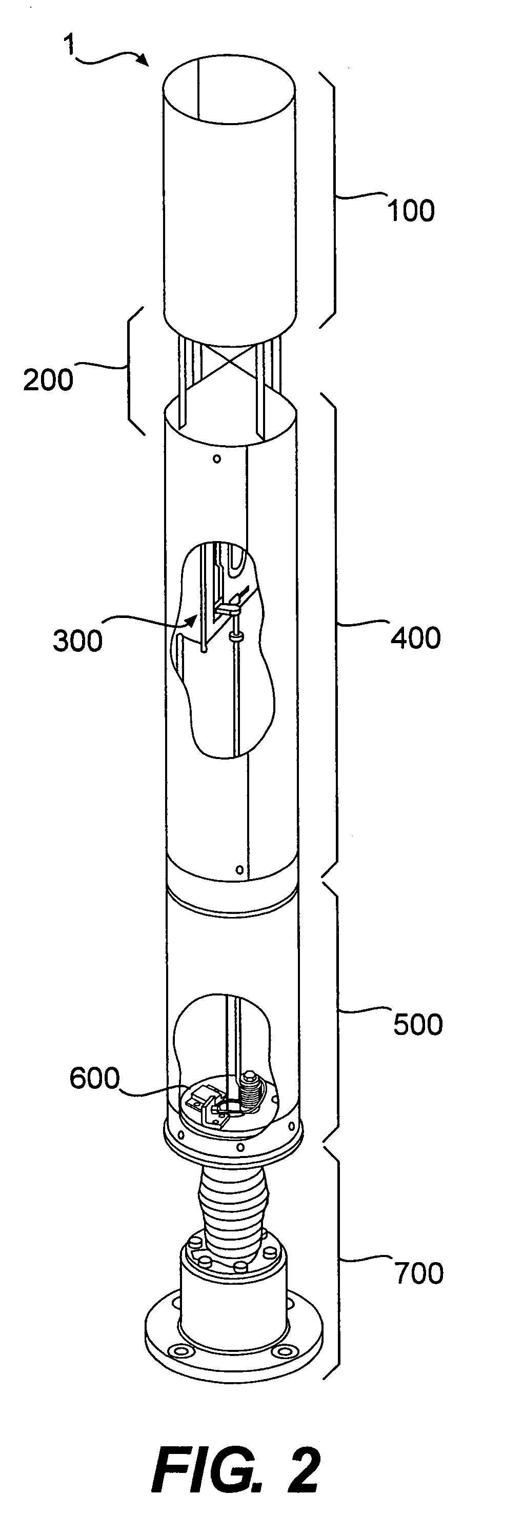
[0064]Referring now to FIG. 2 showing the major component sub-systems of the present invention, ultra-broadband antenna system 1 preferably comprises upper cylinder 100, cone / rod sub-assembly 200, balun sub-assembly 300, lower cylinder 400, canister sub-assembly 500, choke sub-assembly 600, and spring / base sub-assembly 700.

[0065]Referring now to FIG. 3, the major component sub-systems of the present invention 1 preferably are connected to each other as follow...


PUM


Abstract

An ultra-broadband antenna system is disclosed. The antenna system is a single tubular antenna structure comprising an asymmetrical dipole fed with a biconical dipole. The biconical dipole covers the high frequency spectrum, while the asymmetrical dipole covers intermediate frequencies. The invention further relates to a combination of the two dipole structures such that together they act as a monopole to cover the low frequency spectrum. A first RF connector attaches to the asymmetrical dipole and the biconical dipole, and a second RF connector excites the combination of the two dipoles as one large monopole. A choke minimizes interference between the asymmetrical / biconical dipoles and the monopole. The resulting frequency span is greater than 500:1, providing operation over the range of 20 MHz to 10 GHz.

Description

FIELD OF THE INVENTION[0001]The present invention relates to an ultra-broadband antenna system, and more particularly, to a single tubular antenna structure comprising an asymmetrical dipole fed with a biconical dipole. The biconical dipole covers the high frequency spectrum, while the asymmetrical dipole covers intermediate frequencies. The invention further relates to a combination of the two dipole structures such that together they act as a monopole to cover the low frequency spectrum. The resulting frequency span is greater than 500:1.BACKGROUND OF THE INVENTION[0002]In the second millennium, electronic devices are ubiquitous, and it is certain that the number, variety and sophistication will continue to proliferate. Many of these universally available electronic devices employ radio frequency (RF) signals, including radios, televisions, cellular phones, computers, etc. In addition, more and more electronic devices are now activated by remote controls or wireless modems that tr...

Claims


Application Information

Patent Timeline
Patent Type & Authority Patents(United States)
IPC IPC(8): H01Q13/00
CPCH01Q5/00H01Q9/18H01Q9/32H01Q5/357H01Q5/25H01Q5/35H01Q21/30
Inventor LALEZARI, FARZIN
Owner FIRST RF CORP
Why Eureka
Try Eureka