
WDM optical communication system capable of monitoring temperature

a technology of optical communication system and temperature monitoring, which is applied in the field of wavelength division multiplexed passive optical network temperature monitoring and wavelength compensation within the wdm system, can solve the problems of increasing the cost of the system, and affecting the transmission performance of channels

Inactive Publication Date: 2008-03-04
SAMSUNG ELECTRONICS CO LTD
View PDF3 Cites 7 Cited by
  • Summary
  • Abstract
  • Description
  • Claims
  • Application Information

AI Technical Summary

Benefits of technology

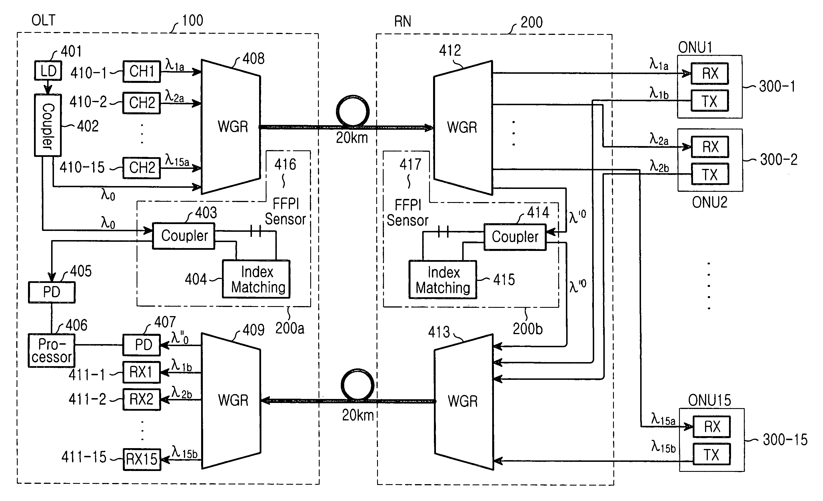
[0022]An object of the present invention is to provide a device in a WDM optical communication system capable of monitoring temperature, that can prevent disagreement of pass wavelength bands by comparing output waveforms from fiber Fabry-Perot interferometer sensors installed at routers at an optical line terminal and a remote node with each other and controlling the router in the optical line terminal to have the same temperature as that of the router in the remote node.
[0023]Another object of the present invention is to solve a problem in that the shift of a wavelength due to the influence of temperature occurs in a WGR that is a router of a remote node so that a pass band in the WGR does not coincide with that in a router of an OLT in a WDM optical communication system and to reduce a crosstalk.

Problems solved by technology

Consequently, the wavelength of a WDM light source for downstream transmission and the received wavelength of the WGR at the remote node (or the wavelength of the WGR in the OLT and the wavelength of the WGR in the remote node) may not coincide with each other, resulting in an output loss on channels transmitted.
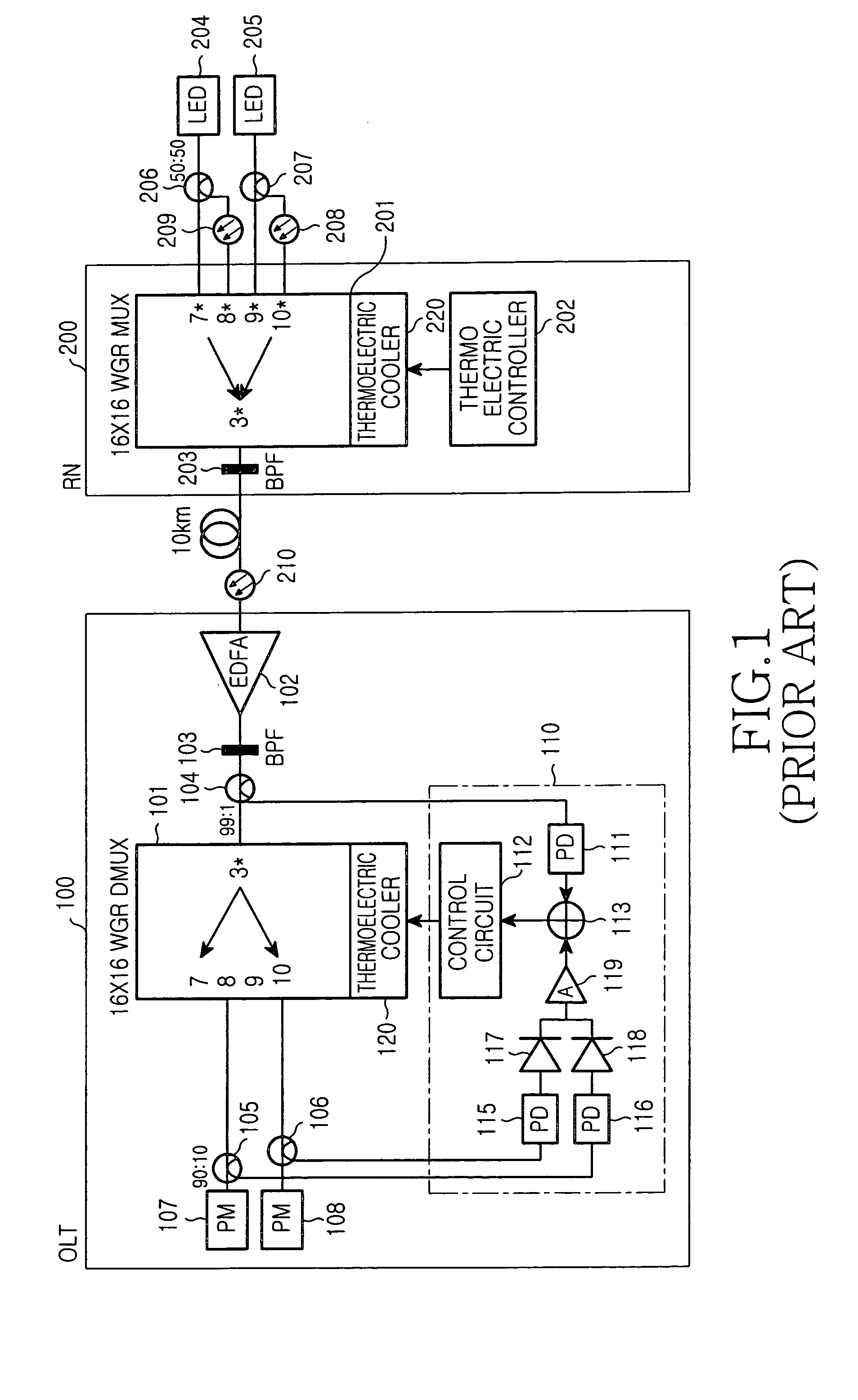
Hence, the transmission performance of a system begins to deteriorate as the temperature in the OLT and / or the remote nodes changes.
Therefore, the cost of a system increases.

Method used


Image

  • WDM optical communication system capable of monitoring temperature
  • WDM optical communication system capable of monitoring temperature
  • WDM optical communication system capable of monitoring temperature

Examples


Embodiment Construction

[0030]Hereinafter, embodiments according to the present invention will be described with reference to the accompanying drawings. For purposes of clarity and simplicity, a detailed description of known functions and configuration incorporated herein will be omitted as it may make the subject matter of the present invention unclear.

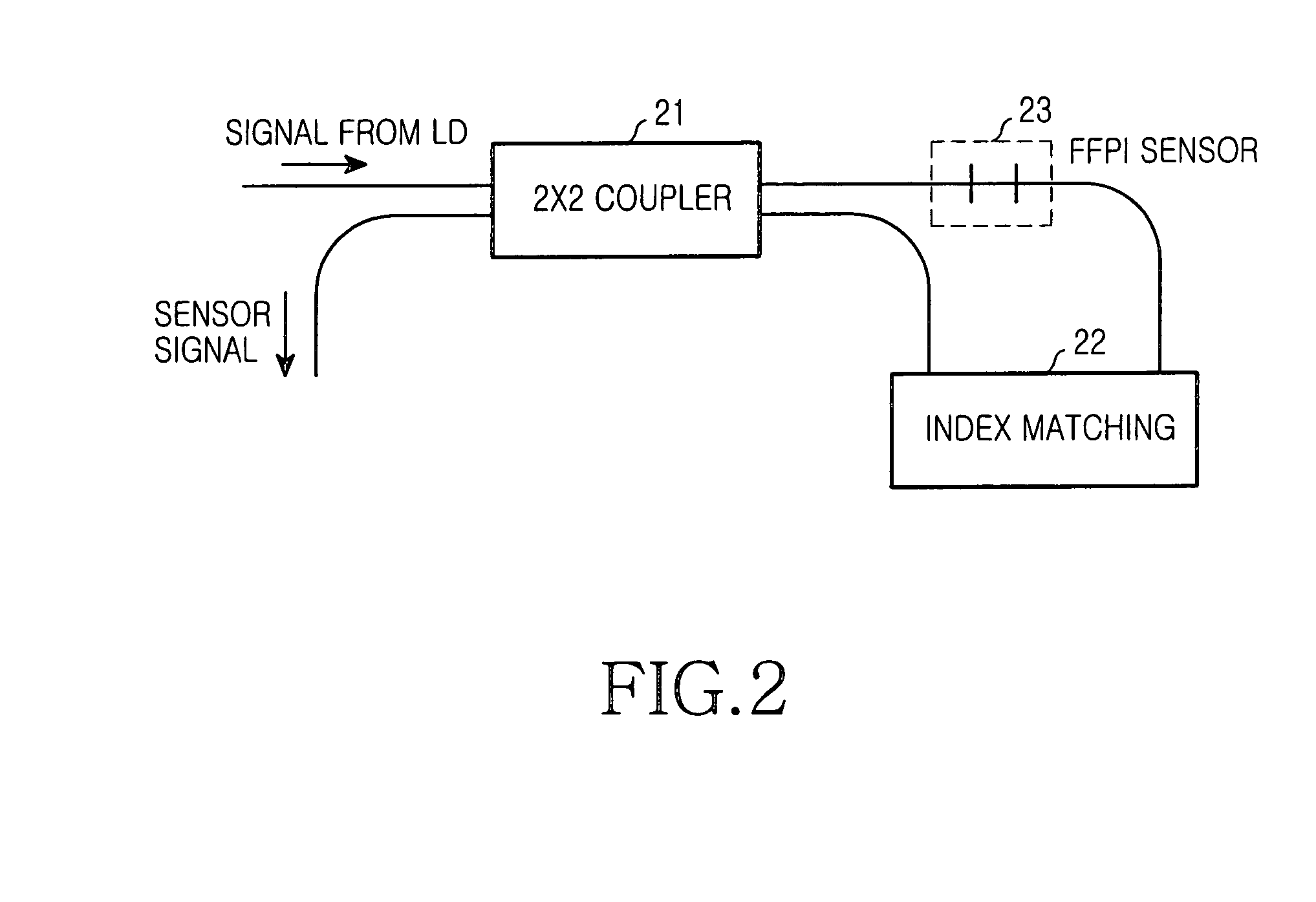
[0031]FIG. 2 is a block diagram showing a construction of an exemplary fiber Fabry-Perot interferometer sensor (FFPI) used in the present invention.

[0032]The FFPI shown includes a 2×2 coupler 21, an FFPI sensor 23, and an index matching unit 22. The 2×2 coupler 21 receives a signal from a laser diode (LD) (not shown) and provides the received signal to the FFPI sensor 23 and employs a signal of the index matching unit 22 as a sensor signal that will be subsequently outputted from coupler 21.

[0033]More specifically, FFPI sensor 23 receives an optical signal from the 2×2 coupler 21, and uses the received signal as an input signal to index matching unit 22 to ...


PUM


Abstract

A device and method to monitor and temperature compensate change in wavelength within a WDM optical communication system is disclosed. The device includes a laser diode for generating an optical signal for temperature monitoring, a first fiber Fabry-Perot interferometer sensor unit for generating a first sensor signal according to temperature by means of the optical signal, and a processor for monitoring temperature by means of the first sensor signal and an externally provided second sensor signal and equalizing waveforms of the two sensor signals with each other. The externally provided second sensor signal is provided by a remote node that includes a second fiber Fabry-Perot interferometer sensor unit for receiving the optical signal for temperature monitoring to generate the second sensor signal according to temperature, and a waveguide grating router unit for transmitting the second sensor signal to the optical line terminal.

Description

CLAIM OF PRIORITY[0001]This application claims priority, pursuant to 35 U.S.C.§119, to that patent application entitled “WDM Optical Communication System Capable of Monitoring Temperature,” filed in the Korean Intellectual Property Office on Sep. 24, 2003 and assigned Serial No. 2003-66354, the contents of which are hereby incorporated by reference.BACKGROUND OF THE INVENTION[0002]1. Field of the Invention[0003]The present invention relates to a wavelength division multiplexed passive optical network, and, more particularly, to temperature monitoring and wavelength compensation within the WDM system.[0004]2. Description of the Related Art[0005]Typical optical subscriber networks use a double star structure in order to minimize the length of an optical line needed to connect the network nodes together. From an optical line terminal (OLT) to a remote node (RN) installed at an area adjacent to the subscriber units, the OLT and RNs are connected via a single strand of optical fiber. The...

Claims


Application Information

Patent Timeline
Patent Type & Authority Patents(United States)
IPC IPC(8): H04J14/02H04B10/08H01S3/00
CPCH04J14/02H04B10/07H04B10/2581
Inventor KWON, SEO-WONLEE, KYUNG-WOOKIM, JIN-HEELIM, SE-YOUNLEE, JONG-HWALEE, YOON-SUNSONG, JAE-YEON
Owner SAMSUNG ELECTRONICS CO LTD
Learn More