
Pulse oximetry ear sensor

a pulse oximetry and ear sensor technology, applied in the field of medical devices, can solve the problems of constricting the ear site of conventional ear sensors, and achieve the effect of constricting the ear site and fast respons

Active Publication Date: 2008-03-11
JPMORGAN CHASE BANK NA
View PDF13 Cites 945 Cited by
  • Summary
  • Abstract
  • Description
  • Claims
  • Application Information

AI Technical Summary

Benefits of technology

[0004]A pulse oximetry sensor may be attached to a variety of tissue sites including a finger, a foot, an ear, a forehead, and the like. An ear site has the advantage of providing a fast response to central changes in oxygenation or lack thereof. Conventional ear sensors, however, have the disadvantage of constricting the ear site because such designs use the monitoring site to secure sensor attachment.
[0006]Another aspect of a pulse oximetry ear sensor are the steps of assembling a sensor with an attachment, positioning the sensor against an ear tissue site with the attachment and supplementing the attachment so as to reduce pressure on said site. A further aspect of a pulse oximetry ear sensor is a sensing means for transmitting and receiving an optical signal to and from a tissue site, an attachment means for securing the sensing means to the site and a supplemental means for assisting the attachment means in securing the sensing means to the site.
[0007]Yet another aspect of a pulse oximetry ear sensor is one or more silicone lenses that can be incorporated into a clip type oximetry sensor and can aid in relieving patient discomfort and pressure necrosis. In one embodiment, the lenses can provide grippy surfaces in contact with the patient's skin, which helps to keep the sensor from slipping off the patient's earlobe or other suitable tissue site. The silicone lenses can also provide pliable contact surfaces that accommodate the patient's skin shape and help to relieve the earlobe or other suitable tissue site from undue pressure. In one embodiment, the clip type sensor includes windows for the optical components of an oximetry sensor that allow for transmission of optical energy to or from a tissue site. The silicone lenses each comprise a translucent silicone material covering the foregoing windows.

Problems solved by technology

Conventional ear sensors, however, have the disadvantage of constricting the ear site because such designs use the monitoring site to secure sensor attachment.

Method used


Image

  • Pulse oximetry ear sensor
  • Pulse oximetry ear sensor
  • Pulse oximetry ear sensor

Examples


Embodiment Construction

[0032]To facilitate a complete understanding of the invention, the remainder of the detailed description describes the invention with reference to the drawings, wherein like reference numbers are referenced with like numerals throughout.

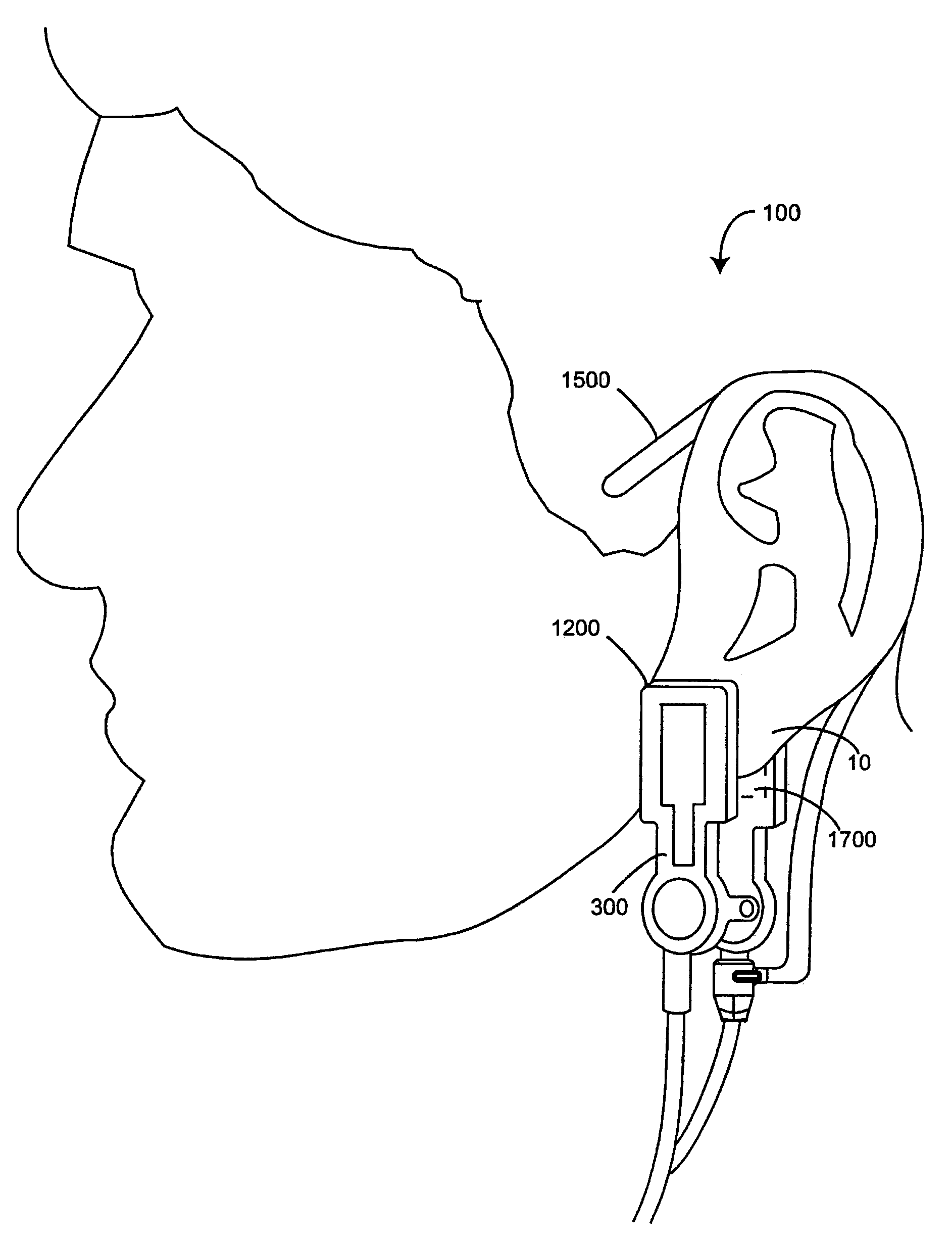
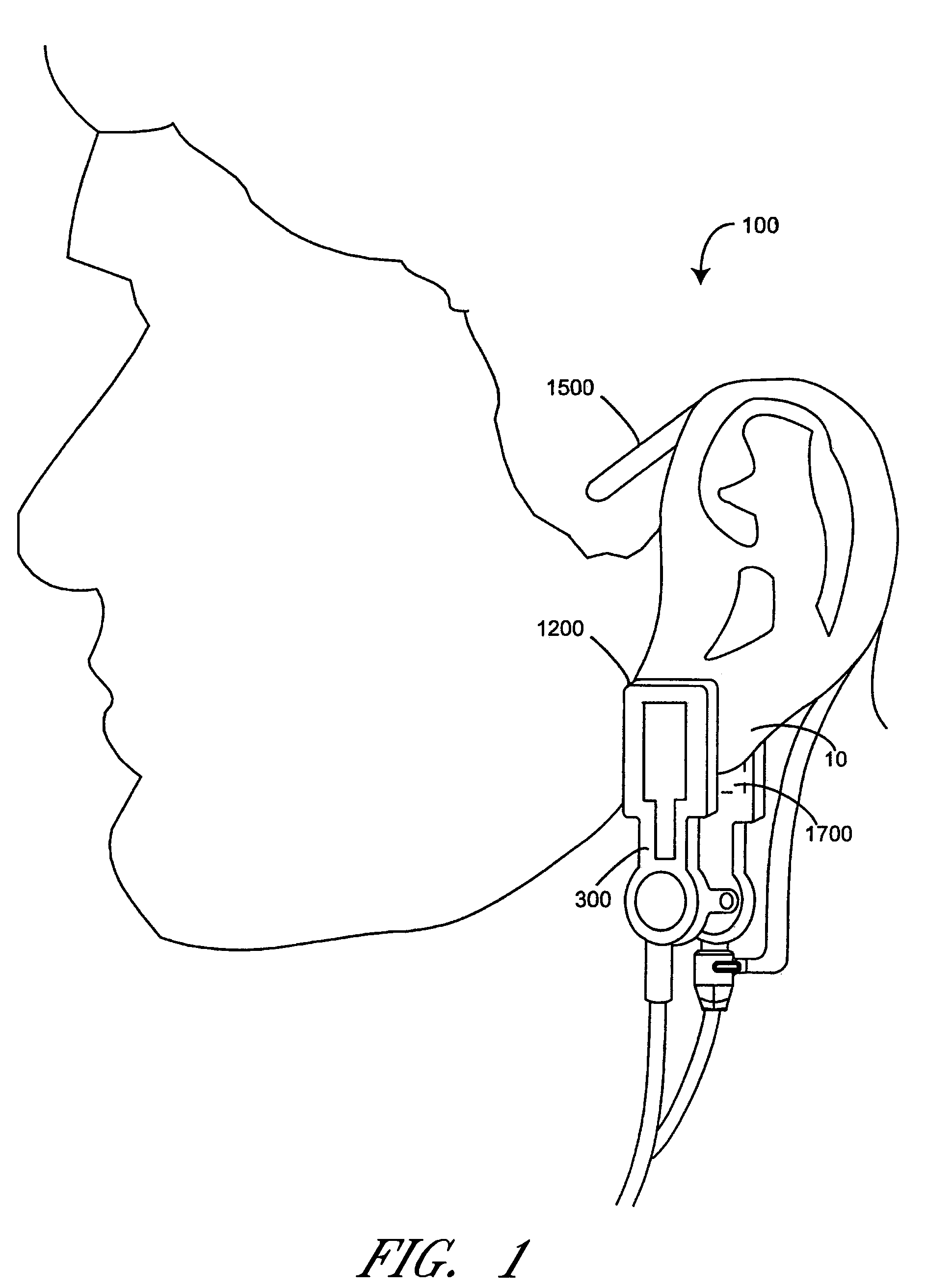
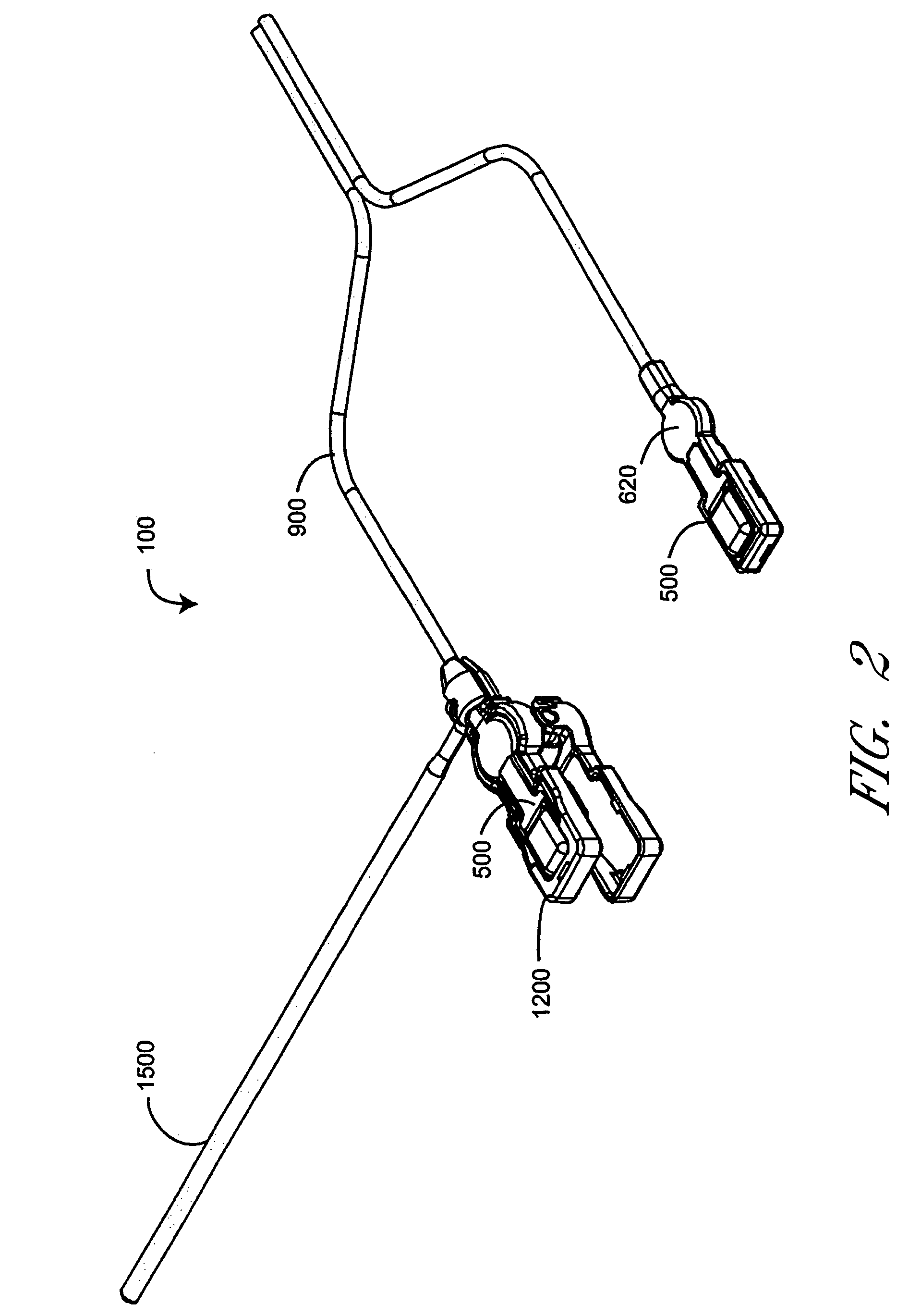
[0033]FIG. 1 illustrates a pulse oximetry ear sensor assembly 100 attached to an ear monitoring site 10. The ear sensor assembly 100 includes an ear sensor 300, a replaceable clip 1200, an ear hanger 1500 and adhesive tabs 1710. The clip 1200 advantageously has a relatively low spring tension and the area of the ear sensor 300 that contacts the ear is relatively large compared with conventional ear sensors, allowing longer monitoring on the ear by reducing patient discomfort and pressure necrosis. To provide secure sensor attachment to the ear site 10, the ear sensor assembly 100 optionally utilizes an ear hanger 1500 and adhesive tabs 1710, individually or in combination, to supplement the clip 1200. The ear hanger 1500 goes around the ear, much lik...


PUM


Abstract

An embodiment of an ear sensor assembly comprises an emitter pad and a detector pad. A clip is configured to removably retain each of the pads. The clip has an open position for placement on an ear tissue site and a closed position for securing the pads to opposite sides of the site. The assembly includes a sensor connector adapted to electrically communicate with a host instrument. A sensor cable has a first end terminating at the pads and a second end terminating at the sensor connector and provides electrical communications between the pads and the connector. In one embodiment, one or more silicone lenses or removable adhesive tabs aid in relieving patient discomfort and pressure necrosis.

Description

REFERENCE TO RELATED APPLICATIONS[0001]The present application claims the benefit of U.S. Provisional Application Nos. 60 / 412,281, filed Sep. 21, 2002, entitled, “Pulse Oximetry Ear Sensor” and 60 / 410,499, filed Sep. 14, 2002, entitled, “Pulse Oximetry Ear Sensor,” the disclosures of which are incorporated by reference herein.FIELD OF THE INVENTION[0002]The present invention relates to the field of medical devices. More specifically, the invention relates to pulse oximetry sensors.BACKGROUND OF THE INVENTION[0003]Pulse oximetry is a noninvasive procedure for measuring the oxygen saturation level of arterial blood, an important parameter in critical patient care applications. Pulse oximeters generally perform a spectral analysis of the pulsatile component of arterial blood in order to determine the relative concentration of oxygenated hemoglobin, the major oxygen carrying constituent of blood, to depleted hemoglobin. A pulse oximetry system includes of a sensor and a monitor. The sen...

Claims


Application Information

Patent Timeline
Patent Type & Authority Patents(United States)
IPC IPC(8): A61B5/00
CPCA61B5/14552A61B5/6816
Inventor SCHULZ, CHRISTIANKIANI, MASSI E.MASON, EUGENE
Owner JPMORGAN CHASE BANK NA
Learn More